Fuel cell stack compression systems, and fuel cell stacks and fuel cell systems incorporating the same

a fuel cell stack and compression system technology, applied in the field of fuel cell stacks, can solve the problems of end plates and tie rods adding considerable weight to the fuel cell stack, and achieve the effect of increasing electrical conduction and reducing electrical resistan

Inactive Publication Date: 2006-05-04
IDATECH LLC
View PDF76 Cites 173 Cited by
  • Summary
  • Abstract
  • Description
  • Claims
  • Application Information

AI Technical Summary

Problems solved by technology

A result of this conventional compression system is that the end plates and tie rods add considerable weight to the fuel cell stack, in addition to any cost and / or size implications of this compression system.

Method used


Image

  • Fuel cell stack compression systems, and fuel cell stacks and fuel cell systems incorporating the same
  • Fuel cell stack compression systems, and fuel cell stacks and fuel cell systems incorporating the same
  • Fuel cell stack compression systems, and fuel cell stacks and fuel cell systems incorporating the same

Examples


Embodiment Construction

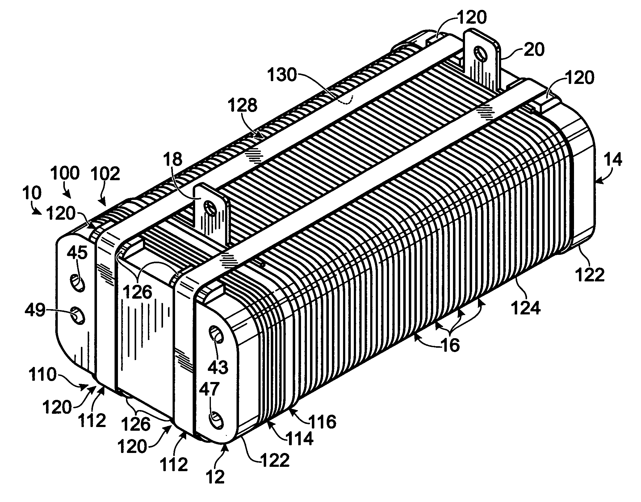
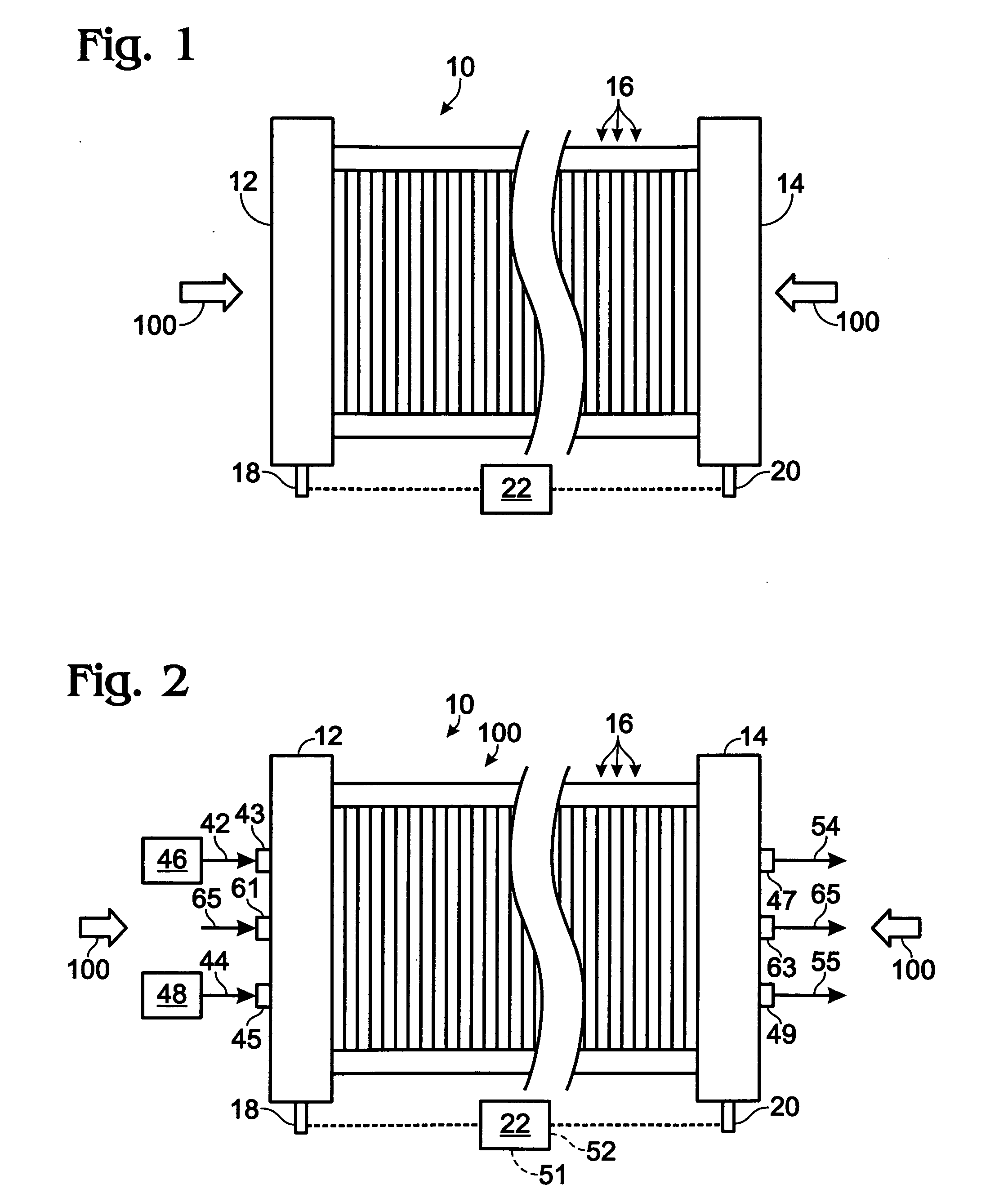
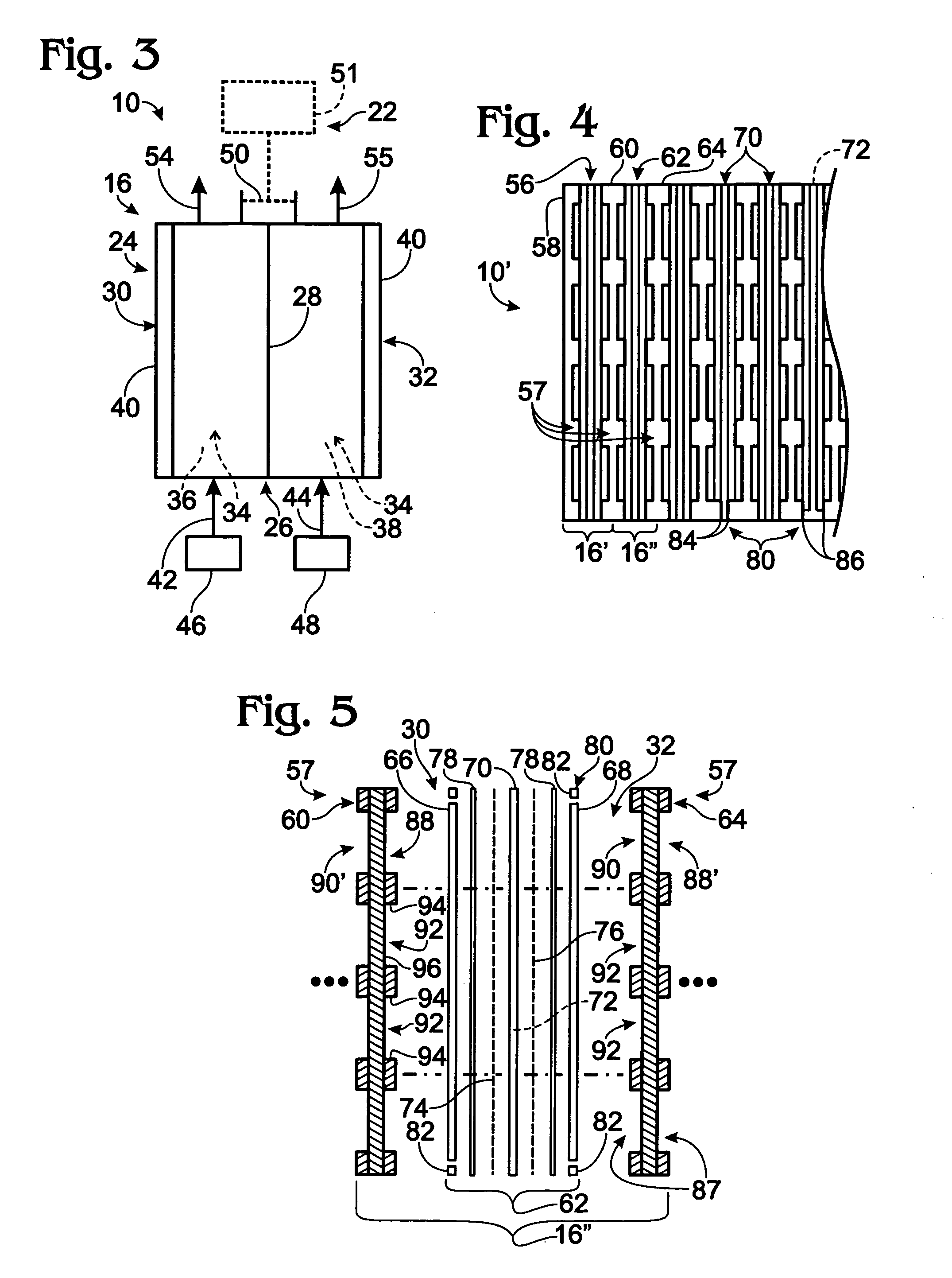
[0039]FIG. 1 schematically depicts a fuel cell stack 10 constructed according to the present disclosure. Stack 10 includes end plates 12 and 14 positioned on opposite ends of the stack. Stack 10 also includes a plurality of fuel cells, or fuel cell assemblies, 16, which are physically arranged between end plates 12 and 14. Each cell is individually configured to convert fuel and an oxidant into an electric current. The fuel cells are electrically coupled in series, although it is within the scope of the disclosure to couple the cells in parallel or in a combination of series and parallel. When electrically coupled, the cells collectively provide an electric potential dependent on the configuration of the stack. For example, if all cells of the fuel cell stack are electrically coupled in series, the electrical potential provided by the stack is the sum of the cells' respective potentials. Therefore, if each fuel cell produces 0.6 volts, then a stack having ten cells in series would h...


PUM

PropertyMeasurementUnit
rated power outputaaaaaaaaaa
rated poweraaaaaaaaaa
rated power outputsaaaaaaaaaa

Abstract

Fuel cell stack compression systems, and fuel cell stacks and fuel cell systems containing the same. The compression systems include banded, framed, and / or segmented compression systems. In some embodiments, the compression systems include at least one compressive band that extends around the end plates and fuel cells, such as in a closed loop. In some embodiments, the banded compression systems include a force-directing structure, compressive inserts, and / or band positioning mechanisms. In some embodiments, the compression systems include a frame into which the stacks' end plates and cells are positioned and with which at least one end plate may be integrated. The frame includes a compression mechanism, which may be an adjustable compression mechanism and / or include one or more jacking members and / or a compression plate. In some embodiments the compression systems include toothed, or striated, segments that interconnect the end plates and retain the plates in compression with ratcheting lock assemblies.

Description

RELATED APPLICATIONS [0001] The present application claims priority to U.S. Provisional Patent Applications Ser. Nos. 60 / 623,156 and 60 / 630,710, which were filed on Oct. 29, 2004 and Nov. 23, 2004, respectively, and the complete disclosures of which are hereby incorporated by reference herein for all purposes.FIELD OF THE DISCLOSURE [0002] The present disclosure relates generally to fuel cell stacks, and more particularly to compression systems for fuel cell stacks, and to fuel cell stacks and fuel cell systems utilizing the same. BACKGROUND OF THE DISCLOSURE [0003] Fuel cell stacks are electrochemical devices that produce an electric current from a proton source and an oxidant. Many conventional fuel cell stacks utilize hydrogen gas as the proton source and oxygen, air, or oxygen-enriched air as the oxidant. Fuel cell stacks typically include many fuels cells that are fluidly and electrically coupled together between common end plates. Each fuel cell includes anode and cathode regi...

Claims


Application Information

Patent Timeline
Patent Type & Authority Applications(United States)
IPC IPC(8): H01M8/24H01M8/10
CPCH01M8/248H01M2008/1095Y02E60/50
Inventor STEINBRONER, MATTHEW P.
Owner IDATECH LLC
Why Eureka
Try Eureka