Car battery post fixing structure

Inactive Publication Date: 2006-05-04
PERNG TE YU
View PDF6 Cites 1 Cited by
  • Summary
  • Abstract
  • Description
  • Claims
  • Application Information

AI Technical Summary

Benefits of technology

[0006] A primary objective of the present invention is to provide a battery post fixing structure that is convenient to install, and, moreover, provides greater safety.
[0008] Based on the aforementioned structure, when installing, the fixing caps are slipped onto each of the battery posts, and because the inside wall of the fixing cap is provided with the screw thread, and the bottom opening is provided with four grooves, and, moreover, because the battery posts assume a slight taper-shape, thus, the closer the fixing cap is to a base of the battery post, the more a base of the fixing cap is pushed open. Furthermore, the screw thread on the inside wall of the fixing cap can further add to tapping of the lead battery post. When the cap nut is configuredly slipped onto the fixing cap, rapid and convenient tightening of the pushed open fixing cap onto the battery post is realized. Because each of the battery posts and the fixing structures are in tight contact, and, moreover, contact surfaces are enclosed interior of the fixing cap, thus, not only is production of sparks reduced, moreover, explosions caused by the sparks coming in contact with gases produced from the battery are prevented. Hence, safety aspect of the structure is enhanced, and oxidation of the battery posts is avoided, thereby achieving effectiveness of prolonging service life of the battery posts.

Problems solved by technology

The locking pieces b2 are often not securely tightened during installation or become loose when the car is moving, which not only prevents the battery a from storing electricity, moreover, sparks are produced.
If the fixing ferrule b has not been firmly tightened, during driving of the car, because car body jumps about continuously, sparks are produced at the battery posts, and there is a possibility of the battery exploding.

Method used


Image

  • Car battery post fixing structure
  • Car battery post fixing structure
  • Car battery post fixing structure

Examples


Embodiment Construction

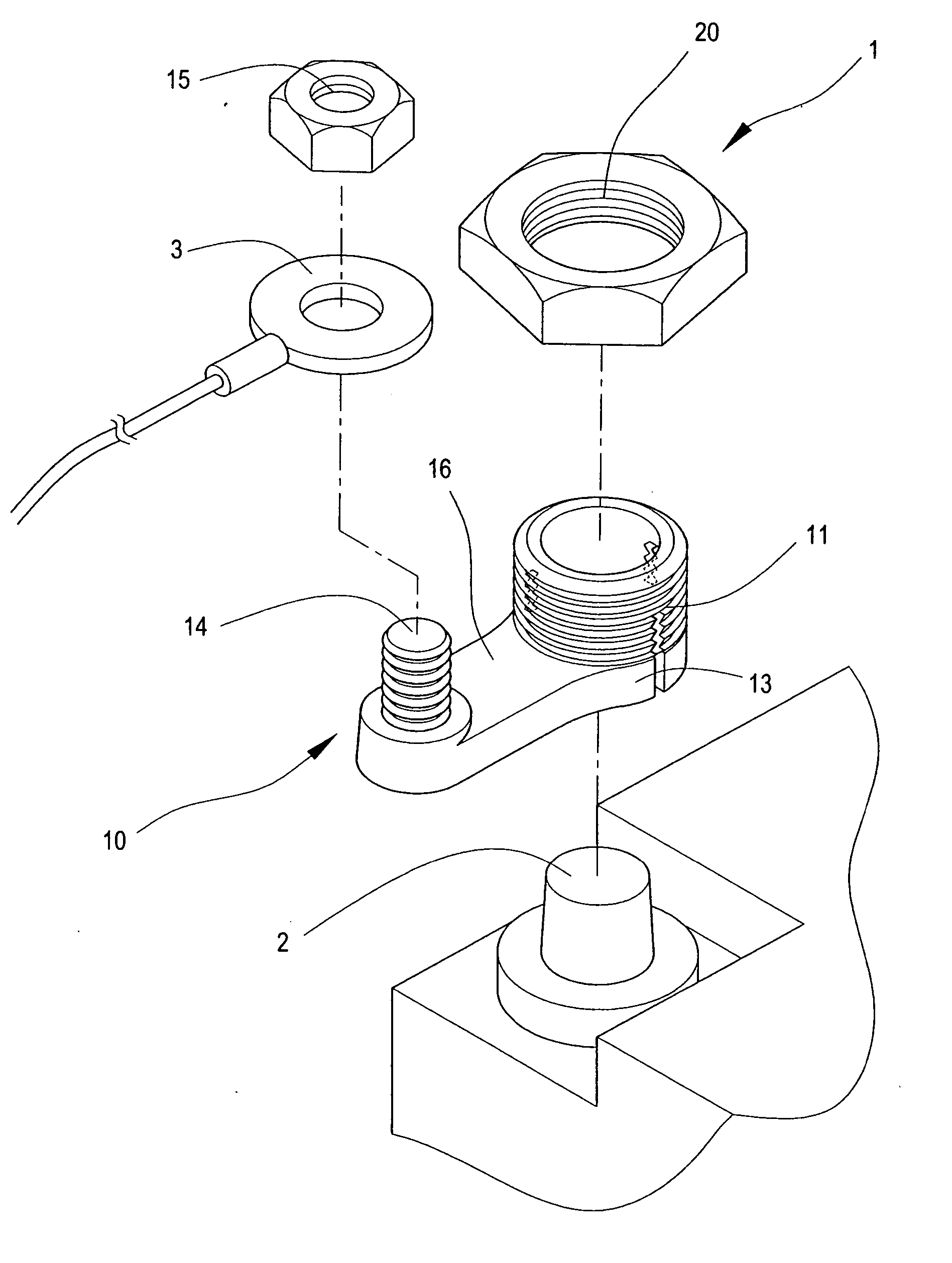
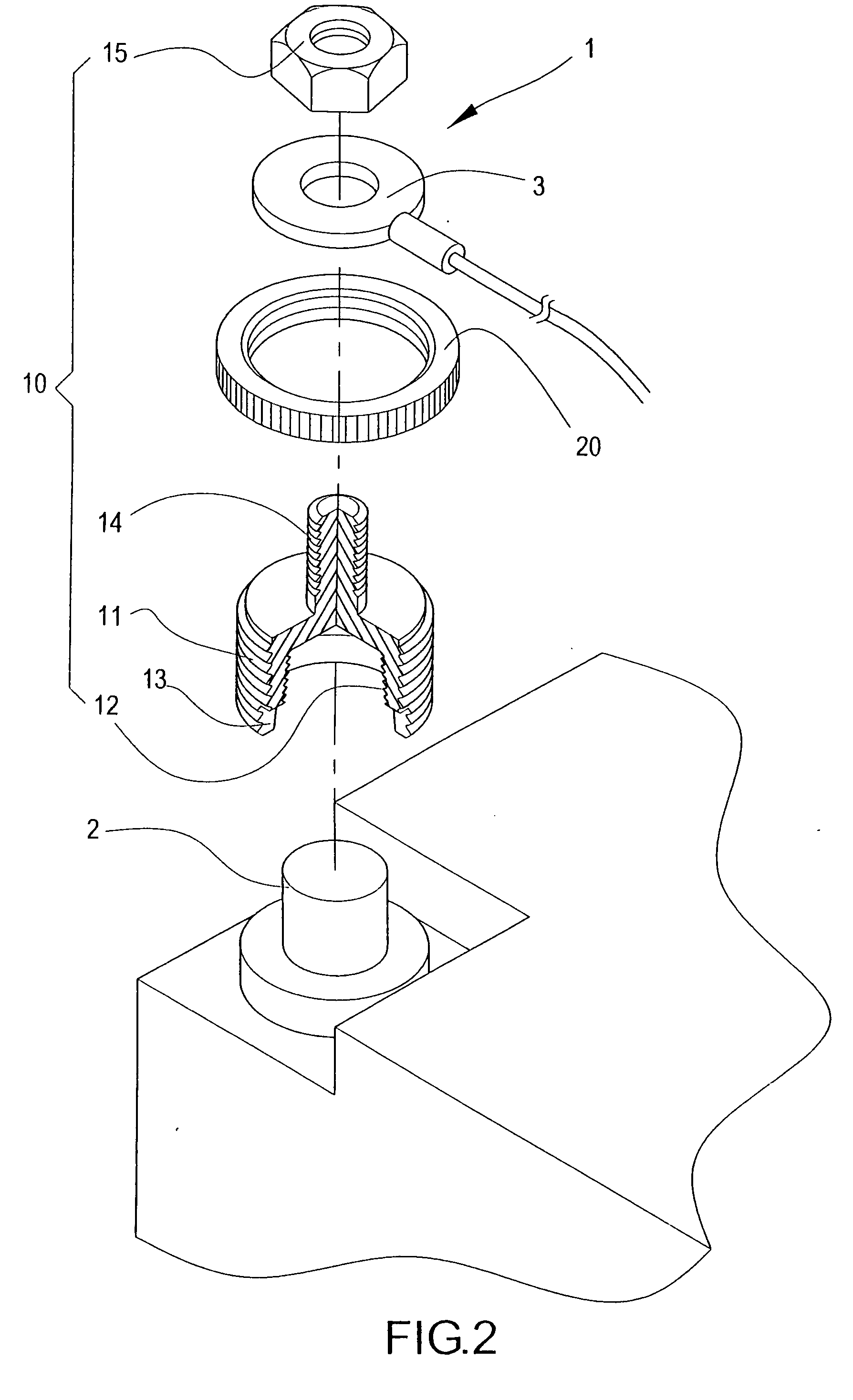
[0017] Referring to FIGS. 2, 3, and 4, which show a car battery post fixing structure of the present invention structured to comprise a fixing cap 10 and a cap nut 20, wherein interior of the fixing cap 10 is formed to correspond to same shape of a battery post 2, and internal diameter of the fixing cap 10 is slightly smaller than that of the battery post 2. A screw thread 11 is configured on an outside wall of the fixing cap 10, and a screw thread 12, which is of type that is in a inverse direction to that of the screw thread 11 of the outside wall, can be configured on an inside wall of the fixing cap 10 or the inside wall is of a smooth threadless type. Moreover, a plurality of grooves 13 are defined on a side edge of an opening of a bottom portion of the fixing cap 10. An extended screw 14 is configured on a top portion external of the fixing cap 10, and which is utilized for a terminal 3 of a car electrical system to slip thereon, whereupon a fixing nut 15 firmly screws down th...


PUM


Abstract

A car battery post fixing structure for installation on a car battery post structure enables facilitating connection with terminals of a car electrical system. The invention includes a fixing cap and a cap nut, wherein a screw thread is configured on an outside wall of the fixing cap, which allows the cap nut to screw down thereon. Furthermore, a screw thread is in an inverse direction to that of the screw thread of the outside wall, is configured on an inside wall of the fixing cap, moreover, a plurality of grooves are defined on a side edge of an opening of a bottom portion of the fixing cap. An extended screw is configured on a top portion of the fixing cap, and when installing, rigid tightening of the fixing cap onto a battery post is realized, which not only achieves convenience in installing, moreover, provides greater safety.

Description

BACKGROUND OF THE INVENTION [0001] (a) Field of the Invention [0002] The present invention relates to a car battery post fixing structure, and more particularly to the fixing structure that is fitted atop a car battery post structure, which thereby facilitates connecting with terminals of a car electrical system. [0003] (b) Description of the Prior Art [0004] Referring to FIG. 1, which shows a conventional car battery post structure connected to an internal negative, positive plate. Electric current is released by means of a chemical change within a car battery, and electricity flows through a connection between post fixing structures and electrical system terminals of a car, thereby supplying the electric current required by the car. Majority of post structures a1 utilized by a car battery a are of a cylindrical form, and after first fixing a ferrule b on the post structure a1, the electrical system terminal of the car can then be firmly connected thereto. The fixing ferrule b is s...

Claims


Application Information

Patent Timeline
IPC IPC(8): H01R4/38
CPCH01R11/281H01R11/283H01R11/287
Inventor PERNG, TE-YU
Owner PERNG TE YU
Why Eureka
Try Eureka