Building construction components

a technology for building components and components, applied in the direction of girders, joists, window/door frames, etc., can solve the problems of increasing costs, affecting the development and advancement of urban renewal plans in many cities, and the dream of owning a newly constructed home out of the economic reach of many families

Inactive Publication Date: 2006-05-11
DIETRICH IND
View PDF70 Cites 58 Cited by
  • Summary
  • Abstract
  • Description
  • Claims
  • Application Information

AI Technical Summary

Problems solved by technology

However, over the years, the rising costs of lumber and labor required to install wood framing components have placed the dream of owning a newly constructed home out of the economic reach of many families.
Likewise, such increasing costs have contributed to the slowing of the development and advancement of urban renewal plans in many cities.
Other problems such as the susceptibility to fire and insect damage, rotting, etc. are commonly associated with wood building products.
The use of such screws, however, creates undesirable buildups which can lead to drywall finishing problems.
In the alternative, the components may be welded together which adds to assembly time and expense.
These components are also commonly coupled together with screws 49 which can lead to drywall finishing problems.

Method used


Image

  • Building construction components
  • Building construction components
  • Building construction components

Examples


embodiment 620

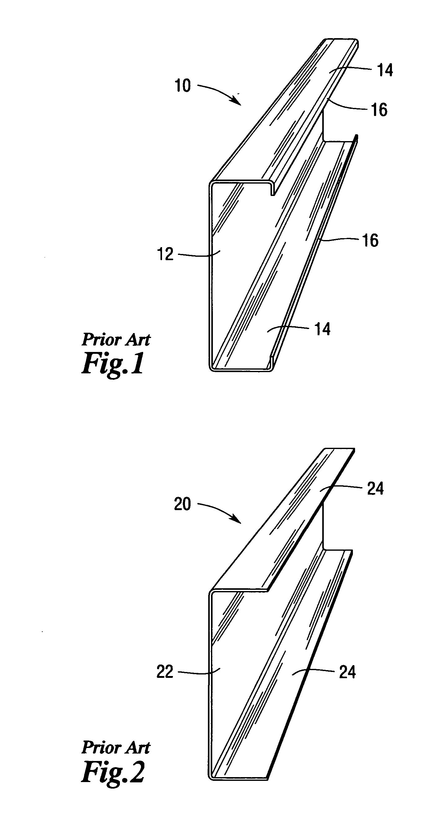
[0129]FIGS. 22 and 23 illustrate an alternative stud embodiment 620 of the present invention. Stud 620 includes a web 622, a first flange 624 and a second flange 626. The first and second flanges (624, 626) protrude outwardly from the web 622. A first leg 628 protrudes from the first flange 624 such that the first leg 628 is substantially parallel to the web 622. Likewise, a second leg 630 protrudes from the second flange 626 such that it is substantially parallel to the web 622. A first return 632 protrudes from the first leg 628 and a second return 634 protrudes from the second header leg 630. See FIG. 22.

[0130] In one embodiment, the stud 620 is rollformed from steel sheet by utilizing conventional rollforming methods and equipment. For example, the stud 620 may be fabricated from 12, 14, 16, 18, 20, etc. gage steel or other metal or material. In this embodiment, the stud 620 may further include a series of stiffener ribs. More particularly and with reference to FIG. 22, the web ...

embodiment 1000

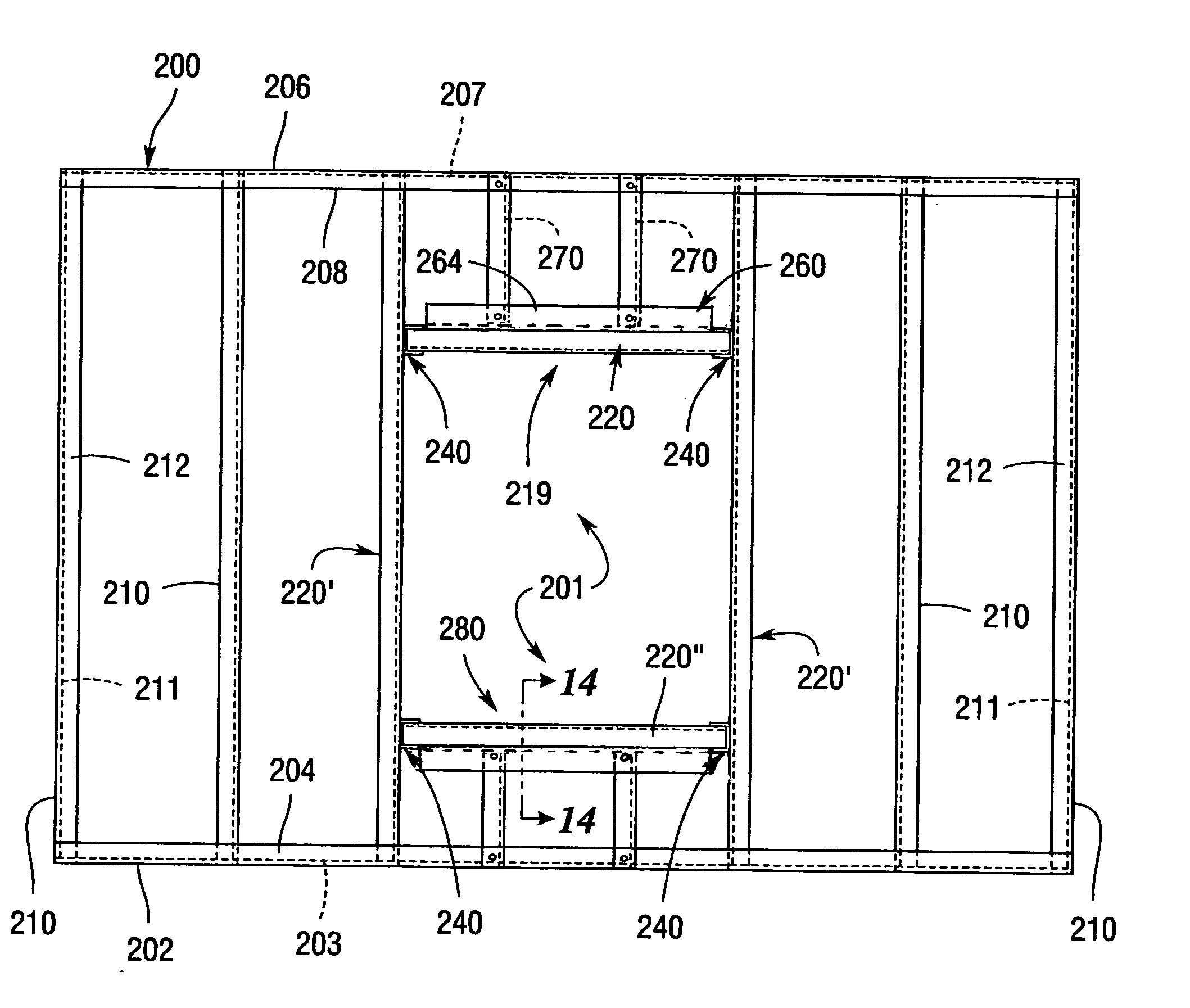
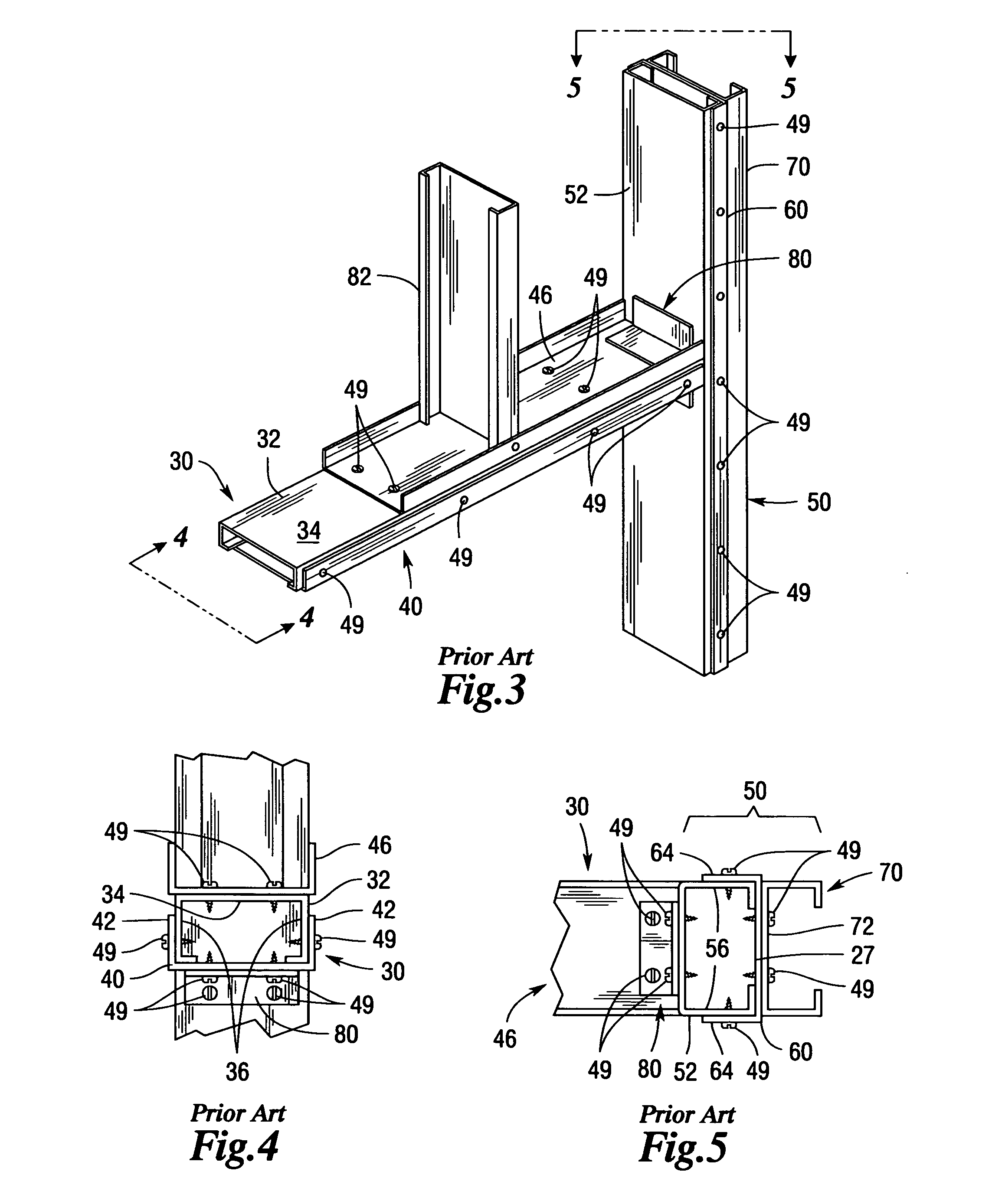
[0145] The connector 810 of the present invention may also be effectively used in connection with header studs 220 of the type and construction described above. In particular and with reference to FIGS. 30 and 31, a header assembly embodiment 1000 of the present invention is depicted for use in connection with a conventional jamb stud 50. In this embodiment, header assembly 1000 includes a pair of header studs 220 that are arranged such that the first leg 228 of one header stud 220 is in abutting contact with the first leg 228 of the other header stud 220. Likewise, the second leg 230 of the one header stud 220 is in abutting contact with the second leg 230 of the other header stud 220 as shown in FIGS. 30 and 31.

[0146] A pair of connector plates 810 is used on each end of the header assembly 1000 to attach one end of the header assembly 1000 to the corresponding jamb stud 50. Fasteners 892 such as 10-16 screws, etc. are inserted through the holes in the connector plate 812 of the c...


PUM


Abstract

Header and jamb stud arrangements, truss assemblies, and support posts are disclosed. The assemblies employ a stud that has a web, a pair of flanges protruding from the web, a leg protruding from each flange and a return formed on the end of each leg.

Description

CROSS-REFERENCE TO RELATED APPLICATIONS [0001] This application is a continuation-in-part application of U.S. patent application Ser. No. 11 / 093,804, entitled Building Construction Components, filed Mar. 30, 2005 which is a continuation-in-part of U.S. patent application Ser. No. 10 / 981,868, entitled Building Construction Components, filed Nov. 5, 2004, the disclosures of which are herein incorporated by reference.BACKGROUND OF THE INVENTION [0002] 1. Field of the Invention [0003] The invention relates to building construction components and, more particularly, to building construction components fabricated from metal such as headers, sills, trusses, girders and support posts. [0004] 2. Description of the Invention Background [0005] Traditionally, the material of choice for new residential and commercial building framing construction has been wood. However, over the years, the rising costs of lumber and labor required to install wood framing components have placed the dream of ownin...

Claims


Application Information

Patent Timeline
IPC IPC(8): E06B1/04
CPCE04B1/24E04B2001/2415E04B2001/2418E04B2001/2439E04B2001/2448E04B2001/2457E04B2001/2463E04B2001/2472E04B2001/405E04C3/07E04C3/11E04C2003/0417E04C2003/0439E04C2003/0452E04C2003/0465E04C2003/0473E04B2001/389
Inventor DAUDET, LARRY RANDALL
Owner DIETRICH IND
Why Eureka
Try Eureka