
Caseless, complete round and also a method of manufacturing such a caseless, complete round

a complete round and caseless technology, applied in the field of complete ammunition rounds, can solve the problems of unfit round use, complicated method and arrangement, and limited possible length of the case, and achieve the effects of increasing the range, increasing the energy content, and good inherent robustness of the block powder

Inactive Publication Date: 2006-05-11
BOFORS DEFENCE
View PDF11 Cites 9 Cited by
  • Summary
  • Abstract
  • Description
  • Claims
  • Application Information

AI Technical Summary

Benefits of technology

[0018] A main object of the present invention is to produce a new type of complete ammunition round primarily, but not exclusively, for electrothermochemical weapon systems, which ammunition round is constructed in such a way that it considerably reduces or completely eliminates all the abovementioned problems and then in particular the need for an essentially dimensionally stable and / or load-bearing case for normal storage, handling and use of the round, the risk of a cartridge case burning on and also other negative effects resulting from combustion residues of a case in the barrel and chamber.
[0028] By replacing the previously used granulated loose powder with multi-perforated, progressive block powder, it has been possible to produce ammunition with an increased energy content, which has resulted in it being possible to increase the range further in comparison with conventional ammunition. By utilizing the very good inherent robustness of the block powder, it has been possible to connect a block-powder charge to the desired shell projectile and a bottom piece comprising a firing device to form a caseless but nevertheless complete round which can be loaded as a coherent unit.

Problems solved by technology

It goes without saying that such a case has a clearly limited possible length in relation to the diameter of the round and the thickness of the case because an elongate round with a thin case is easily broken by its own weight or the weight of the projectile.
It is clear that, if the round is placed upside down during handling, the projectile will make a hole in the casing, which renders the round unfit for use.
U.S. Pat. No. 5,183,961 describes a very complicated method and arrangement for attempting to reduce this considerable risk of bursting of the barrel in the event of incorrect ignition of a front propellent charge located alongside the projectile.
A considerable problem with the construction shown is that the entire inner, extremely complex arrangement of ignition strand tubes, holders, spacers etc. including the rigid case has to be assembled before the loose powder is poured into the case via a filling hole arranged specially for the purpose in the bottom piece of the round.
The manufacturing time and cost for this very complicated construction are therefore considerable.
All these extra elements moreover constitute additional component parts which form disadvantageous residual products when firing takes place.
The main technical problems which form the basis of the present invention have consequently been the excessive weight of the conventional case, the inadequate rigidity and strength of the lightweight cases, the negative effects of the inevitable residual products and also the number of extra component parts which have to be added in order to obtain a desired ignition process, and a desire to produce a caseless round in which no loads have to be taken up by a case.

Method used


Image

  • Caseless, complete round and also a method of manufacturing such a caseless, complete round
  • Caseless, complete round and also a method of manufacturing such a caseless, complete round

Examples


Embodiment Construction

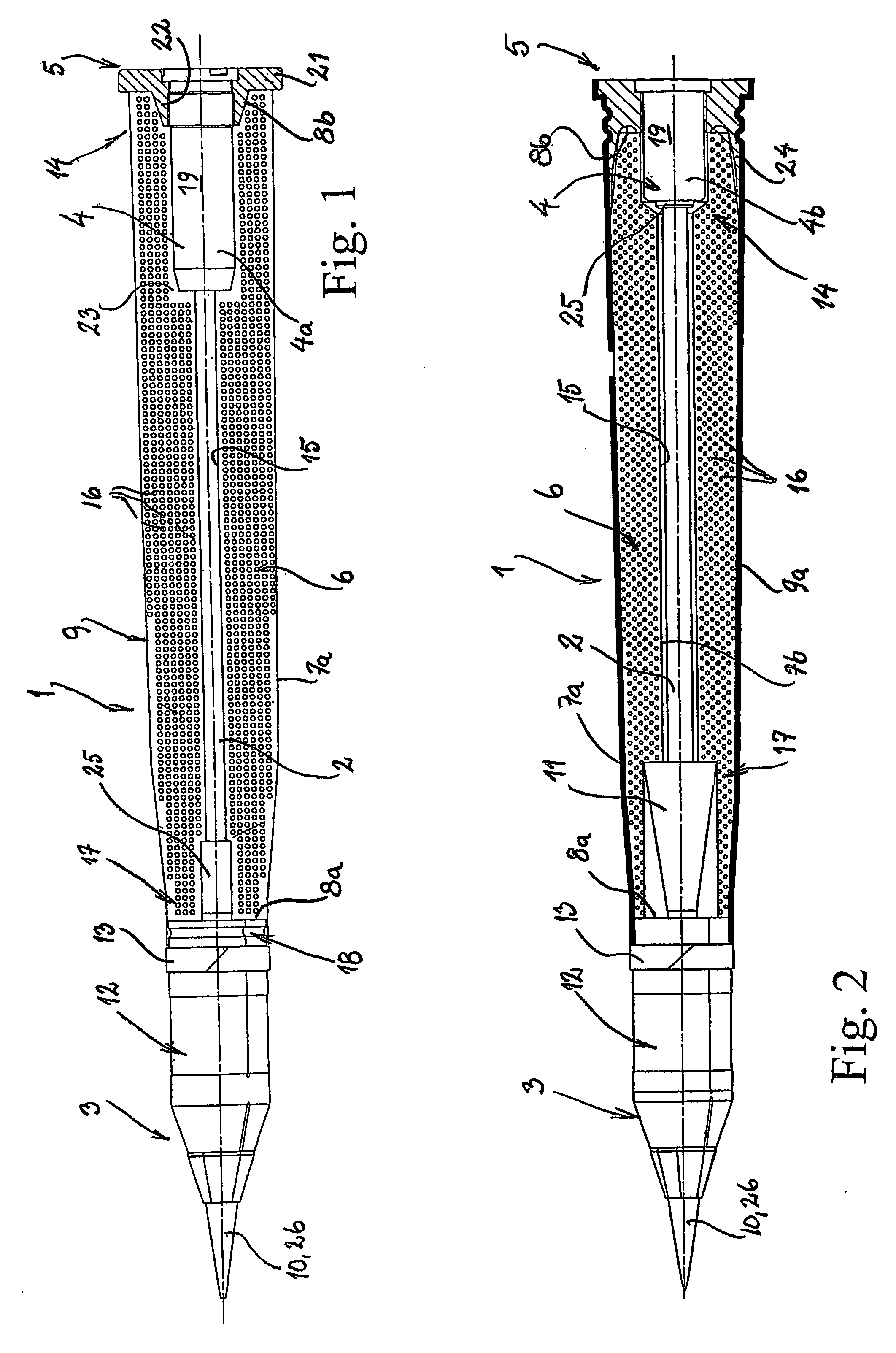
[0033] With reference to FIG. 1, a caseless, large-calibre, complete ammunition round 1 according to a first embodiment of the present invention is shown diagrammatically. The round 1 is preferably, but not exclusively, intended for artillery pieces, anti-tank guns and tank cannons. Accordingly, it is entirely possible for the present invention to be used in more small-calibre ammunition as well.

[0034] The round 1 comprises a load-transferring and load-absorbing, elongate inner component 2, for example a rod or a tube made of a suitable, preferably combustible, material made of, for example, metal, plastic etc., which is mounted between a front dart projectile 3 shown in the figure and a rear firing device 4 which is screwed detachably into a bottom piece 5 made of, for example, combustible material, suitably a fibre composite. However, the bottom piece 5 can also be metal. The round 1 also comprises a cartridge-shaped propellent charge 6 which is arranged around, that is to say so...


PUM


Abstract

The invention also relates to a method of manufacturing and use of the ammunition round in other more conventional weapon systems than the said electrothermal and / or electrothermochemical weapon systems.

Description

TECHNICAL FIELD [0001] The present invention relates to a complete ammunition round intended to be loaded as a coherent unit primarily in electrothermal and / or electrothermochemical weapon systems, which round comprises a propellent charge for propulsion of a projectile through a barrel and which projectile is arranged on the front end of the propellent charge, a bottom piece which is arranged on the rear end of the propellent charge, and a firing device arranged, preferably detachably, on the bottom piece. [0002] The invention also relates to a method of manufacturing a caseless, complete ammunition round which is loaded as a coherent unit primarily in electrothermal and / or electrothermochemical weapon systems, which round comprises a propellent charge which propels a projectile through a barrel and which projectile is arranged on the front end of the propellent charge, a bottom piece which is arranged on the rear end of the propellent charge, and a firing device arranged, preferab...

Claims


Application Information

Patent Timeline
IPC IPC(8): F42C19/08F42B5/18
CPCF42B5/18F42B5/181F42C19/0826
Inventor STARK, OLAGUSTAVSSON, LENNART
Owner BOFORS DEFENCE
Learn More