Method for electrical flashover ignition and combustion of propellent charge, as well as propellent charge and ammunition shot in accordance therewith

a technology of propellent charge and ignition, which is applied in the direction of combustion ignition, lighting and heating apparatus, combustion process, etc., can solve the problems of high load weight, limited possible increase in velocity in respect of a given loading space, and high load weight. , to achieve the effect of increasing the load weight of ammunition, increasing the load weight, and increasing the load spa

Inactive Publication Date: 2013-12-17
BAE SYST BOFORS
View PDF11 Cites 10 Cited by
  • Summary
  • Abstract
  • Description
  • Claims
  • Application Information

AI Technical Summary

Benefits of technology

[0049]The primary concept behind the present invention is now that the ignition of the particular multiperforated propellant shall be carried out electrically via the thin electrically conductive surface coating, hereinafter referred to, therefore, as the ignition coating, without any form of separate igniter, such as percussion primer or ignition generator, inserted inside the propellant or the ammunition. Since the thin surface coating is in itself electrically conductive, it only needs to be connected to a respective input and output line of the electrical high-voltage source in order for ignition and plasma formation to be realized, so that, where a metal ammunition case is used, the ammunition case is expediently disposed against an external electrical contact on the bottom of the case and another on its neck, whereby an electric circuit is obtained. Where an electrically insulated case is used, either coated with or made of electrically insulating material, two electrical transmission points are instead arranged through the case insulation to said electrically conductive surface coating. As a result, the loading space is gained which would otherwise have to be utilized for the igniter. This loading space which is hence released can thus be utilized to increase the load weight for the ammunition and thus the effect of the charge and of the ammunition. At the same time, the very use of geometric units of multiperforated propellant components in the charge already implies possibilities of making up compact propellent charges with very high load weights and thus with very high energy content, at the same time as the electrical ignition principle according to the present invention implies a possibility for the momentary flashover ignition of all propellant components incorporated in the particular propellent charge, both along their outer sides and inside the burning channels of all these components, by virtue of the fact that the burning surfaces thereof are provided with electrically conductive ignition coatings. Taken together, all this provides a very good progressivity with wholly predetermined energy development and exact burning time for propellent charges of this type, at the same time as the risk of emergence of the pendulum pressures which are so dreaded in an artillery context has been able to be wholly eliminated.
[0050]Another advantage of the electrical ignition principle according to the invention is that this is very well suited to the initiation of propellent charges in so-called telescopic ammunition, i.e. such ammunition in which the projectile itself is disposed far into the space which is otherwise primarily taken up by the propellent charge and in which, therefore, parts of the propellent charge surround the rear part of the projectile. An often occurring problem with such ammunition has namely previously been that the flashover ignition of the propellent charge easily became uneven, in that the rear part of the projectile screened off parts of the propellent charge in the flashover ignition and during the continued combustion process, resulting in the emergence of the aforementioned pendulum pressure.
[0051]The electrical ignition principle according to the invention in a more refined form states that each propellant component in its entirety is coated with a surface-covering ignition coating, or that at least the majority of all the free outer burning surfaces of propellant components incorporated in the propellent charge, as well as the inner burning surfaces of all burning channels originating therefrom, are provided prior to the ignition with an electrically conductive surface coating, which, upon the desired initiation of the propellant, is connected to a high-voltage source, whereupon said ignition coating is converted into an electrically conductive plasma, see further clarification below, which instantaneously ignites the propellant over all the burning surfaces provided with said surface coating, i.e. that a surface-coating plasma is produced. In multiperforated propellants, it is thus an advantage if the electrically conductive surface coating (the ignition coating) also extends down into all perforations and other holes, etc. which have been arranged with the aim of constituting burning channels or burning surfaces, since an instantaneous flashover ignition of the propellant is then obtained even inside and along these spaces and surfaces. It can also be imagined that a propellent charge is first made up out of preferably multiperforated, variously shaped propellant components into a certain propellent charge configuration, for example according to the internal dimension of a particular ammunition case, and is then provided with the electrically conductive ignition coating over its free surfaces and down into the inner surfaces of the burning channels, so that the non-free surfaces placed one against the other thus remain deprived.
[0052]Note that the ignition according to the invention is thus not realized via a slow gradual weak-current heating of a locally situated initiation point until a chemical spontaneous ignition temperature is attained, but rather via a momentary “physical plasmafication”, i.e. a vaporization and ionization of the evaporation gases which have been formed by the electrically conductive surface coating universally at once with the aid of very high electrical energy supplied from the high-voltage source.
[0053]Through utilization of the extremely hot, electrically conductive and, in terms of energy, controllable plasma generated via the high-voltage source and the ignition coating, according to the present invention the sought-after instantaneous and full flashover ignition of all the burning surfaces prepared for flashover ignition is now achieved in even the most compact of all propellent charges with the greatest load weights and the highest propellent charge density which can currently in any way be made up of various configurations of layers, arranged closely together, of shaped geometric units of multiperforated propellant components and types of explosive.
[0054]A further and appreciable advantage with the present invention is thus that it becomes possible to monitor and control the propulsion of the projectile during the whole or parts of the acceleration through the barrel, since additional, in terms of energy, regulatable electrical energy, in addition to the chemical energy from the combustion of the propellent charge, can be supplied to the propulsion via the ionized plasma.

Problems solved by technology

Quite simply, no such measurement specifications are included in these patent specifications, since, when the patents came into being in the 1890's, no suitable instruments were available which made it possible to measure how quickly the gunpowder actually burns.
Moreover, the igniter per se entails a cost, since it is consumed for each fired ammunition shot.
As previously indicated above, the propellent charges can be packed together and / or arranged close together in a variety of fits and volumes, by means of smaller geometric units of multiperforated propellant, and can thereby be given high load weights, which are difficult or very often impossible to achieve in any other way in ammunition.
The possible increase in velocity in respect of a certain given loading space is, however, limited.
With more compact propellent charges, moreover, the problem ensues of how an instantaneous, i.e. momentary, and full flashover ignition of the propellant along all of its burning surfaces intended for flashover ignition shall be able to be achieved.
The aforementioned combustion-gas-driven, progressive ammunition too, however, has a practically possible upper limit for the acceleration of the muzzle velocity, at about 1800 m / s.

Method used


Image

  • Method for electrical flashover ignition and combustion of propellent charge, as well as propellent charge and ammunition shot in accordance therewith
  • Method for electrical flashover ignition and combustion of propellent charge, as well as propellent charge and ammunition shot in accordance therewith
  • Method for electrical flashover ignition and combustion of propellent charge, as well as propellent charge and ammunition shot in accordance therewith

Examples


Embodiment Construction

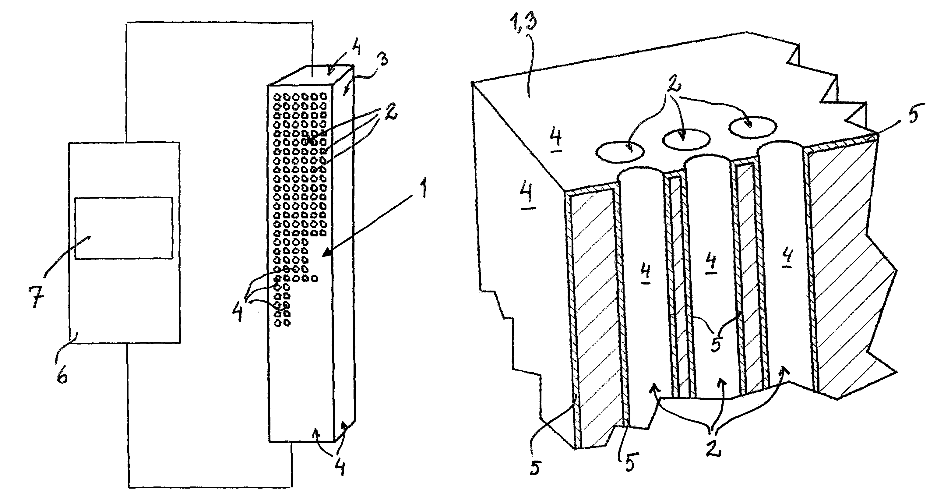
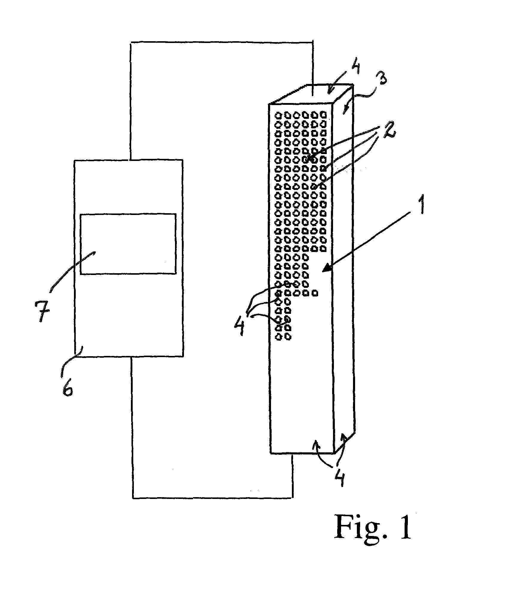
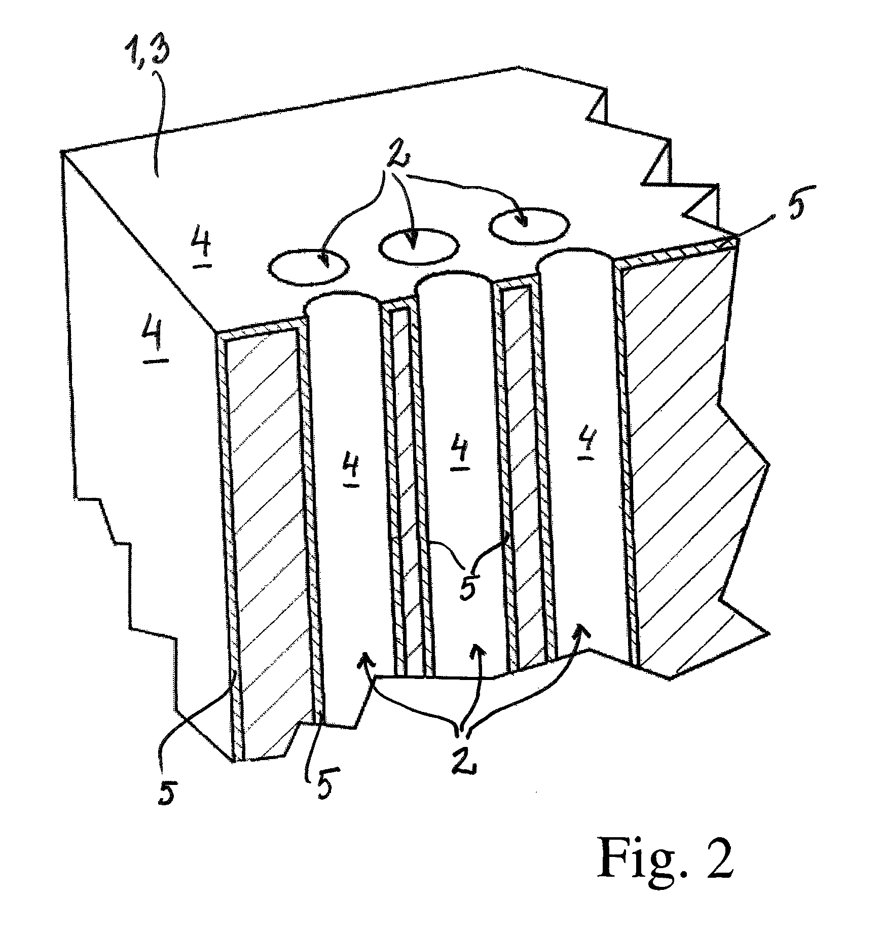
[0060]FIG. 1 shows an embodiment of a multiperforated propellant component 3 incorporated in a propellent charge 1 and multiperforated by means of burning channels 2, here especially in the form of a rectangular propellant block, which, according to the invention, via a covering, electrically conductive surface coating 5 applied over certain or all free burning surfaces 4 existing for ignition, see FIG. 2, (also hereinafter referred to as the ignition coating), has been prepared for an instantaneous electrical flashover ignition, and which propellant component 3, together with other propellant components existing in the particular propellent charge 1, has been connected to a high-voltage source 6 (shown schematically) comprising a pulse unit 7 for the production of a pulsed plasma, which plasma realizes the desired instantaneous flashover ignition (hereinafter referred to as plasma ignition), a controllable progressive combustion of the particular propellent charge 1, as well as a, ...


PUM

PropertyMeasurementUnit
diameteraaaaaaaaaa
ignition temperatureaaaaaaaaaa
electric currentaaaaaaaaaa

Abstract

The invention relates to a method of, in the electrical ignition of a propellent charge (1) provided with an electrically conductive surface coating (5) and comprising one or more propellant components (3), ensuring that ignition and progressive combustion of the propellent charge take place. The method is characterized in that said electrically conductive surface coating, when ignition of the propellent charge is desired, is connected to an electrical high-voltage source (6), in that said high-voltage source is made to generate at least one high electrical pulse to said connected electrically conductive surface coating, and in that said at least one high electrical pulse produces an instantaneous flashover ignition of the electrically conductive surface coating of the propellent charge and of all its propellant components, simultaneously. The invention also relates to a propellent charge and to an ammunition shot comprising the propellent charge.

Description

CROSS REFERENCE TO RELATED APPLICATIONS[0001]This application is a National Phase filing under 35 U.S.C. §371 of PCT / SE2009 / 000151 filed on Mar. 23, 2009; and this application claims priority to Application No. 0800729-6 filed in Sweden on Apr. 1, 2008 under 35 U.S.C. §119; the entire contents of all are hereby incorporated by reference.TECHNICAL FIELD[0002]The present invention relates to a method of, in the electrical ignition of a propellent charge provided with an electrically conductive surface coating and comprising one or more propellant components, ensuring that ignition and progressive combustion of the propellent charge take place.[0003]The present invention also relates to a propellent charge, provided with an electrically conductive surface coating intended for electrical ignition, comprising one or more propellant components, at least one of which is multiperforated with burning channels.[0004]In addition, the present invention relates to an ammunition shot intended to ...

Claims


Application Information

Patent Timeline
Patent Type & Authority Patents(United States)
IPC IPC(8): F42B5/16C06D5/00C06B45/18
CPCF41A19/58F42B5/08F42C19/0811F42B5/16
Inventor STARK, OLAGUSTAVSSON, LENNARTDAHLBERG, JOHANSVANBERG, LARS-PETER
Owner BAE SYST BOFORS
Why Eureka
Try Eureka