
Decoy device and system for anti-missile protection and associated method

a technology of anti-missile protection and decoy devices, applied in the field of anti-missile protection, can solve the problems of sacrificing flight efficiency, using several flares and pellets, and aircraft being susceptible to attacks

Active Publication Date: 2006-05-11
THE BOEING CO
View PDF15 Cites 10 Cited by
  • Summary
  • Abstract
  • Description
  • Claims
  • Application Information

AI Technical Summary

Benefits of technology

The present invention provides a decoy device that can protect a target vehicle from surface-to-air and air-to-air missiles. The decoy device uses a propellant and a catalyst that produce a sufficient amount of heat and pressure to lure the missile away from the target vehicle. The decoy device can be easily installed, inspected, serviced, and removed from the target vehicle. The use of low-toxicity propellants and a heat-sinking tank reduces the risk of secondary issues on the ground. The decoy device can also be used in conjunction with other defensive mechanisms, such as chaff, explosives, or decoys.

Problems solved by technology

Aircraft may be susceptible to attacks from surface-to-air and air-to-air missiles.
However, several flares and pellets must be used since the pellets are incapable of maintaining flight once deployed.
As a result, the aircraft must be equipped with several flares that may be used for a single missile since the pellets eventually burn out, which may ultimately sacrifice flight efficiency by increasing weight and the amount of space required on the aircraft for the flares.
Even with respect to kinematic flares, the flares typically employ a fuel that burns out of control once ignited, which increases the potential for ground fires.
In addition, the burning fuel tends to produce toxic byproducts.

Method used


Image

  • Decoy device and system for anti-missile protection and associated method
  • Decoy device and system for anti-missile protection and associated method
  • Decoy device and system for anti-missile protection and associated method

Examples


Embodiment Construction

[0024] The present invention now will be described more fully hereinafter with reference to the accompanying drawings, in which some, but not all embodiments of the invention are shown. Indeed, this invention may be embodied in many different forms and should not be construed as limited to the embodiments set forth herein; rather, these embodiments are provided so that this disclosure will satisfy applicable legal requirements. Like numbers refer to like elements throughout.

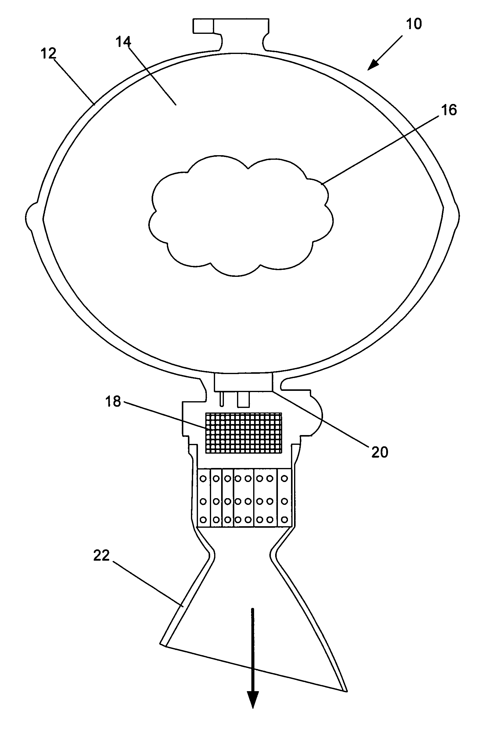
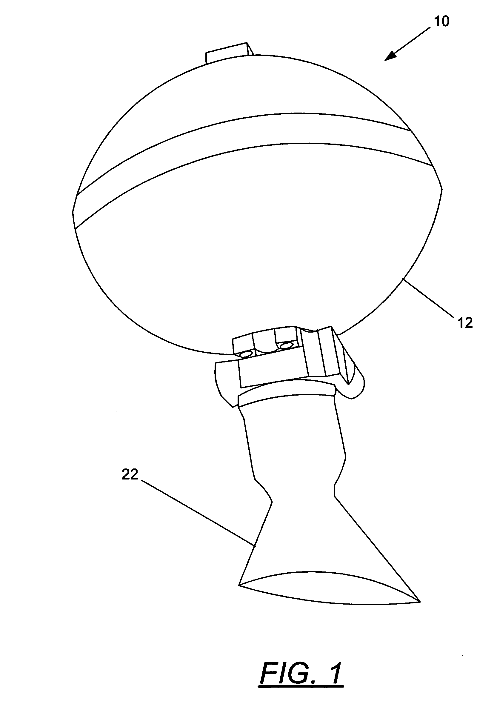
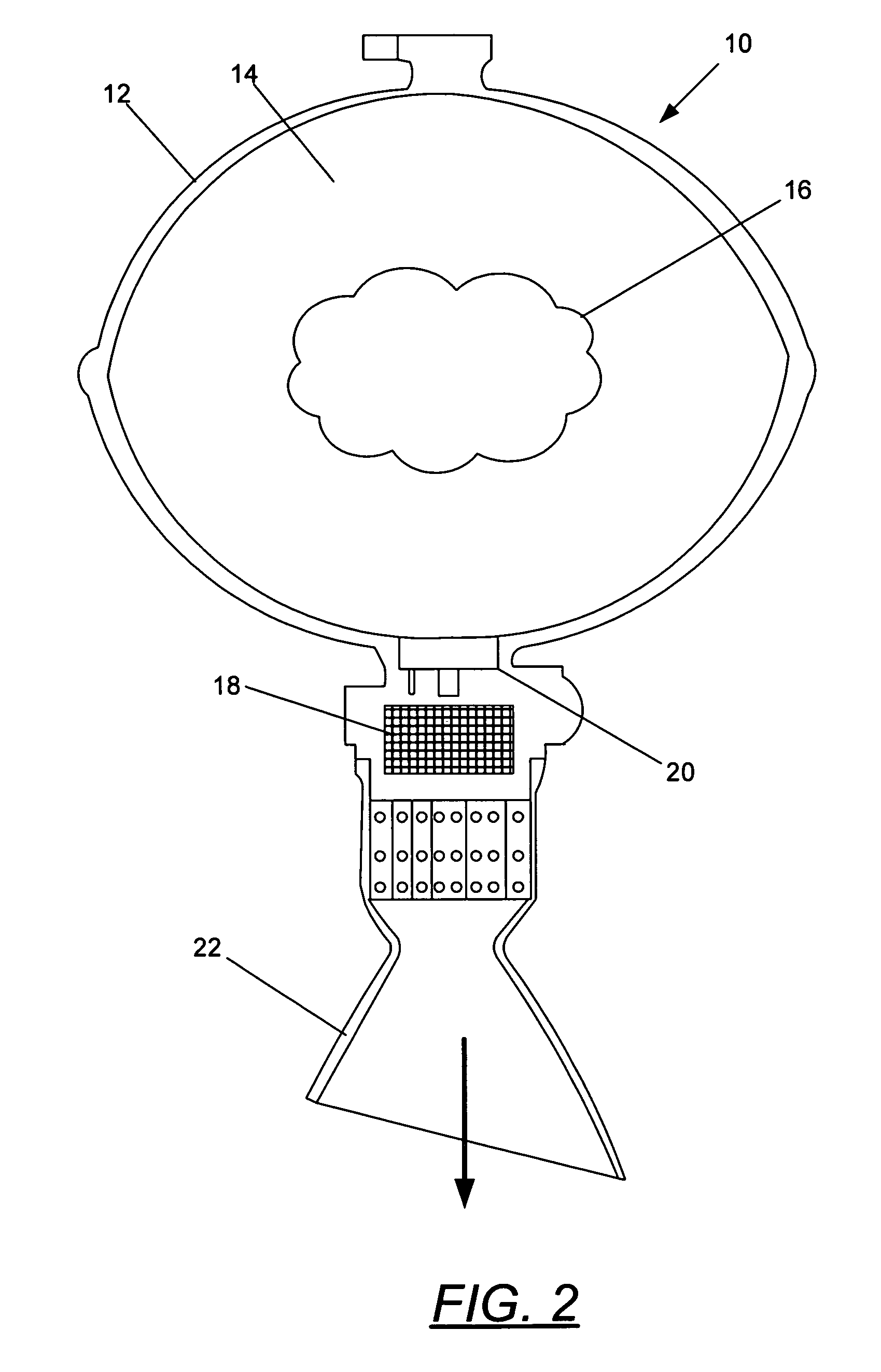
[0025] Referring now to the drawings and, in particular to FIG. 1 there is shown a decoy device 10. The decoy device 10 is capable of using a propellant to provide thrust to the decoy device, as well as serve as a decoy for infrared or heat-seeking missiles such that the missile is lured away from a target vehicle. The decoy device 10, as the term is used herein, is not meant to be limiting and may include any device capable of being deployed from a vehicle and providing anti-missile protection for the vehicle. ...


PUM


Abstract

A decoy device and system for anti-missile protection and an associated method are provided. The decoy device includes a propellant and a tank containing the propellant. The decoy device also includes an outlet defined in the tank, and a catalyst contained within the tank and capable of exothermically reacting with the propellant to emit a gas having a heat and pressure. The heat generated by the reaction is radiated by the decoy device is capable of attracting a missile, while the gas is expelled through the outlet to provide thrust to the decoy device.

Description

BACKGROUND OF THE INVENTION [0001] 1) Field of the Invention [0002] The present invention relates to anti-missile protection, more particularly, to a deployable decoy device for protecting a target vehicle from surface-to-air, air-to-air, or similar missiles. [0003] 2) Description of Related Art [0004] Aircraft may be susceptible to attacks from surface-to-air and air-to-air missiles. These missiles are generally “heat seeking” and employ infrared guidance such that they do not emit signals that may be detected by the target. The infrared-guided missiles typically seek in a specified wavelength and, as such, may detect sources of non-natural radiated energy, such as the emissions of an aircraft engine. [0005] A number of techniques have been developed to protect aircraft from surface-to-air and air-to-air missiles. Flares are the most common devices used as a decoy, although other techniques, such as suppressants, shields and blocking devices, pyrophorics, and directional infrared c...

Claims


Application Information

Patent Timeline
Patent Type & Authority Applications(United States)
IPC IPC(8): F42B10/00
CPCF41H11/02F41J2/02F42B12/70
Inventor SWANSON, JON D.
Owner THE BOEING CO
Learn More