Gel extraction device

a gel extraction and gel technology, applied in the field of biotechnology, can solve the problems of significant variations in the yield of dna purification, affecting the reproducibility of results obtained, and the technique of manual blades is susceptible to a high degree of technique related variability

Active Publication Date: 2006-05-11
LABGADGET LLC
View PDF30 Cites 9 Cited by
  • Summary
  • Abstract
  • Description
  • Claims
  • Application Information

AI Technical Summary

Benefits of technology

[0011] Accordingly, it is a primary objective of the present invention to provide a reliable gel slice extraction device capable of repeatedly cutting clean gel slices from a slab gel for further analysis of any biomolecules contained within an extracted gel slice.
[0012] Still another primary objective of the present invention is to provide a quick and easy single handed means for gel slicing and transferring.
[0014] Another objective of the present invention is to provide a multi-angle gel slicing device capable of cutting samples from most angles of insertion, mainly from a substantially 90° angle desirable for a clean extraction.
[0016] In accordance with an embodiment of the invention, there is provided a gel slice extraction device that cleanly cuts a targeted gel matrix piece and retains the piece for transfer to an appropriate container, the device comprising a hollow cutting member and a plunger ejector member. The hollow cutting member has a tubular proximal portion that tapers gradually to a hollow rectangular distal portion ending in a sharp cutting edge. The tubular proximal portion is fitted with a rim having spring locking tabs for a ribbon spring reception. The plunger ejector includes a proximal end cap atop a split stem portion. Outer opposing legs of the split stem portion have shoulder extensions that act to stop plunger downward action. A middle leg serves as the ribbon spring providing spring action to control plunger ejector progress through the hollow cutting member. The split stem portion terminates in a disk where a solid rectangular distal portion begins. When the gel slice extraction device is assembled, the plunger ejection member rectangular distal portion is slidingly inserted into the hollow cutting member hollow rectangular distal portion and the ribbon spring is engaged by the spring locking tabs. When pressure is applied to the proximal end cap, the ribbon spring is compressed until the shoulder extensions reach the rim. In addition, the solid rectangular portion contacts an embedded gel slice and ejects the gel slice into a suitable container. Release of pressure on the end cap causes the ribbon spring to decompress and return to an at rest position drawing the rectangular distal portion away from the hollow rectangular distal portion sharp cutting edge. Upon return to the at rest position, the device can be re-used repeatedly to achieve the isolation of other gel slices.

Problems solved by technology

Unfortunately the manual blade technique is susceptible to a high degree of technique related variability, which affects the reproducibility of results obtained in subsequent evaluations of the transferred target biomolecule.
Lack of uniformity of gel slices leads to significant variations in DNA purification yields.
However, when a band is diffuse and not well separated from other biomolecules, the blade excision procedure has little chance of producing a clean, reproducible sample.
In addition, differences in the sizes of excised bands can result in significant variability in follow-up activity assays.
Another disadvantage of the blade technique concerns a safety issue generally associated with sharp objects in general whereby users are susceptible to cuts.
In addition, when blades are used to excise gel bands, a further potential health complication exists if the electrophoresis step is carried out with radioactively labeled biomolecules.
A cut to a hand during the band excision process could result in a transfer of potentially dangerous radioactive material directly to a user's skin.
Still another disadvantage of the blade technique is that it requires a separate means for transferring a blade excised gel slice to a suitable container.
A final disadvantage of the blade technique is that blades and tweezers are generally used repeatedly, thereby potentially leading to contamination of subsequent excised gel slices.
Also, it is not clear whether the gel slices actually remain in the tubular cutting tool until the application of compressed air.

Method used


Image

  • Gel extraction device
  • Gel extraction device
  • Gel extraction device

Examples


Embodiment Construction

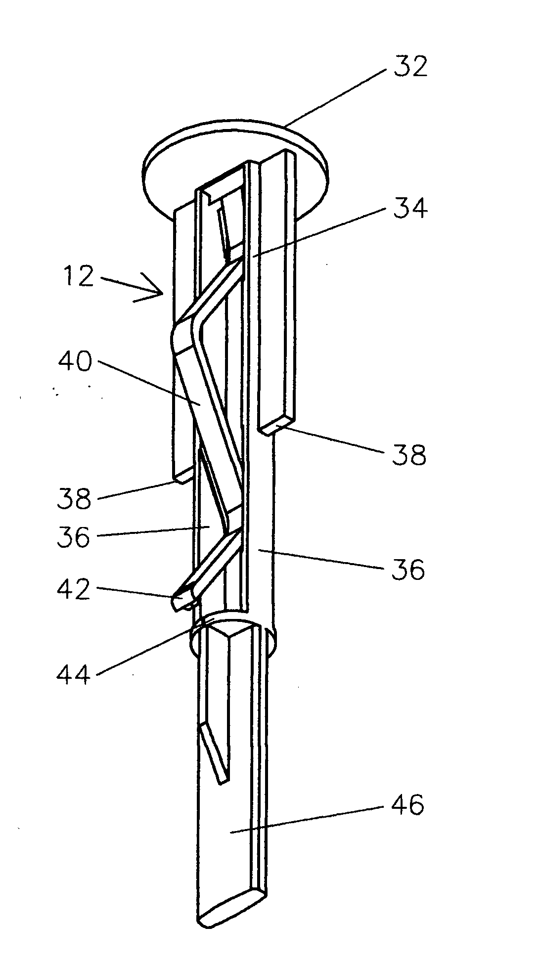
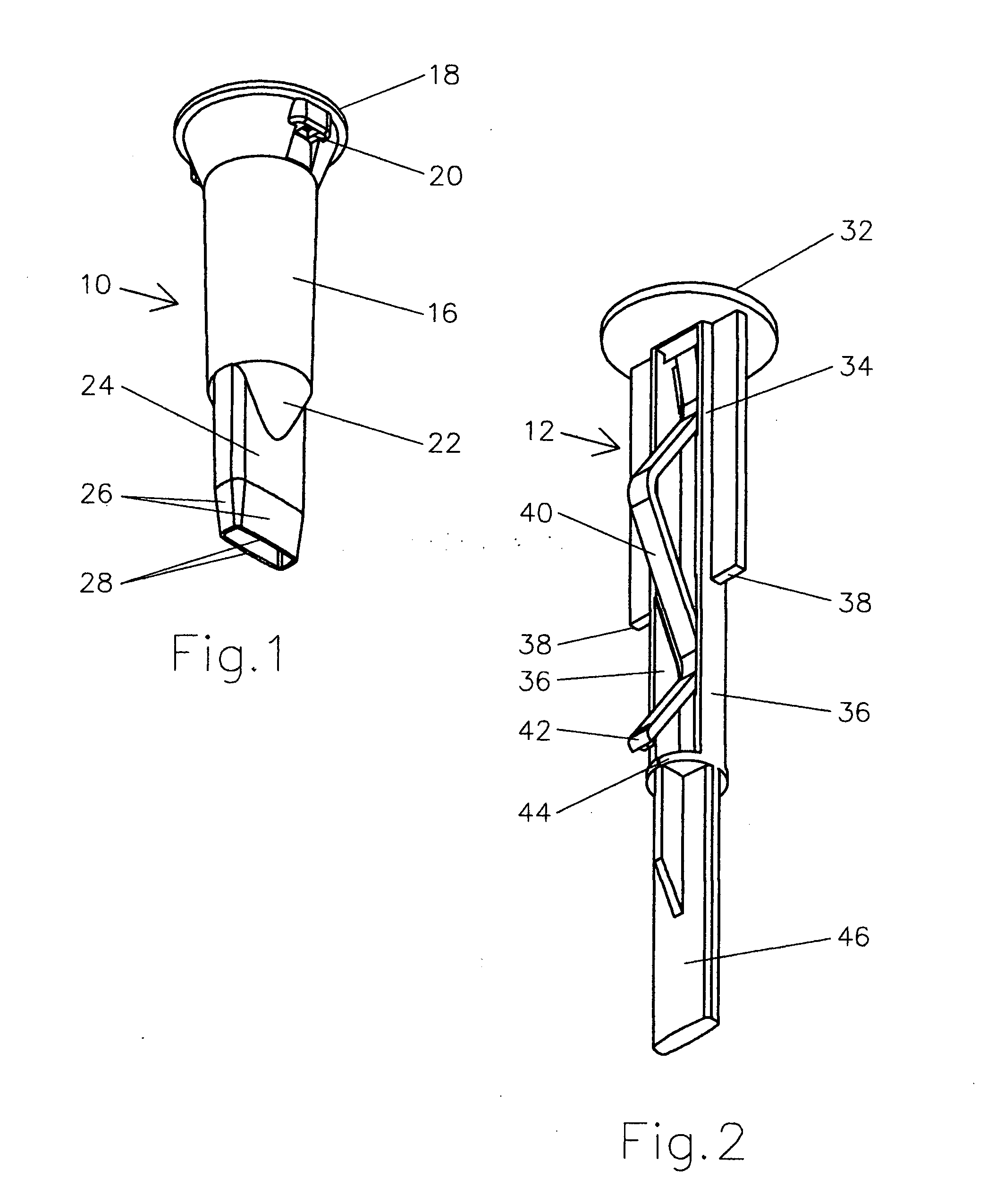
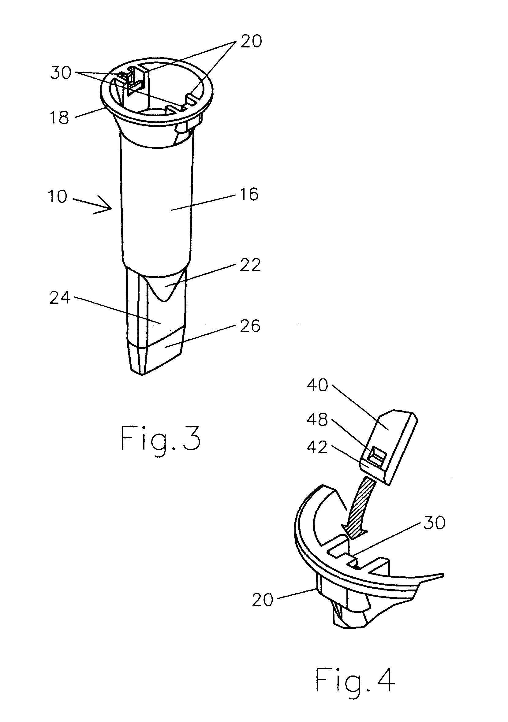
[0040] Referring now to FIGS. 1 and 2 a gel extraction device is described wherein like reference numerals refer to like elements throughout. Also, mutually related components of the present invention are depicted in FIGS. 1 and 2. FIG. 1 illustrates a hollow cutting member 10 that receives a plunger ejector member 12 as illustrated in FIG. 2 to comprise the gel extraction device 14 shown fully assembled in FIG. 5. The hollow cutting member 10 has a proximal tubular body 16 terminating in a circular rim 18, having a pair of oppositely disposed spring engaging structures 20. At an end opposite to the circular rim 18, the hollow cutting member 10 proximal tubular body 16 tapers gradually into a sloped transition portion 22 ending in a rectangular receptacle 24 shaped to accommodate substantially rectangular shaped gel slices, the typical shape of bands of biomolecules obtained by electrophoresis. The rectangular receptacle 24 terminates in a tapered end portion 26 with a perimeter cut...


PUM

PropertyMeasurementUnit
thicknessaaaaaaaaaa
angleaaaaaaaaaa
thicknessaaaaaaaaaa

Abstract

A gel extraction device comprising a hollow cutting member having a cutting edge at one end and a squeeze bulb at the other end. In a further embodiment, the air passage between the cutting edge and the bulb has a constriction zone to prevent any extracted gel from being drawn too deeply into the extractor. In a further embodiment, a blow-hole in the hollow cutting member or in the squeeze bulb provides for the passage of air displaced by gel through the extractor. The blow-hole may be covered to secure the gel in the receptacle for transfer from the matrix to a sample container.

Description

RELATED APPLICATIONS [0001] The present application claims priority from and is a continuation-in-part of U.S. patent application Ser. No. 10 / 871,655 filed Jun. 21, 2004, which is also the parent application of International Patent Application PCT / US / 2005 / 021572 filed Jun. 17, 2005.BACKGROUND OF THE INVENTION [0002] Gel electrophoresis is used extensively in the field of biotechnology to separate target biological macromolecules (biomolecules), such as DNA, RNA, or protein from a mixture of biomolecules. This analytical tool, which utilizes a gel matrix to achieve separation of biomolecules, is used at the research level and also during the manufacturing and quality assurance testing of biomolecules. It is often desirable to remove a target biomolecules from a gel polymer for further analysis. This invention relates to a device for transferring target biomolecules from the gel matrix to a container, such as an Eppendorf tube, for further analysis. [0003] The excision of gel slices f...

Claims


Application Information

Patent Timeline
Patent Type & Authority Applications(United States)
IPC IPC(8): B01L3/00B26D7/18B26F1/32C12M1/16G01N1/06G01N1/08G01N27/447
CPCB26D7/1818B26F1/32G01N1/06G01N1/08Y10T436/25Y10S83/919Y10T436/25375Y10T436/2525G01N27/44717Y10T83/222
Inventor CALDWELL, JEREMYCALDWELL, DALECLOUSER, LEON
Owner LABGADGET LLC
Why Eureka
Try Eureka