
Three-dimensional printing prototyping system

a three-dimensional printing and prototyping technology, applied in the field of three-dimensional printing prototyping system, can solve the problems of long curing time, low curing rate, and relative weak adhesive force, and achieve the effect of shortening the period of tim

Inactive Publication Date: 2006-05-11
KOREA INST OF MACHINERY & MATERIALS
View PDF2 Cites 130 Cited by
  • Summary
  • Abstract
  • Description
  • Claims
  • Application Information

AI Technical Summary

Benefits of technology

The present invention provides a three-dimensional printing prototype system that can significantly shorten the time required to cure a three-dimensional prototype and create a solid three-dimensional prototype. The system includes a prototyping chamber with a movable table, a material containing chamber with a movable table, and a material supplying means for supplying powder material to the prototyping table. The system also includes a printing head for injecting a photocuring adhesive material onto the powder material, a curing device for photocuring the adhesive material, and a control computer for controlling the printing head and curing device. The system can control the powder material to be supplied to the prototyping table and the adhesive material to be injected and cured on the powder material in a region corresponding to the section data of the three-dimensional prototype. The curing device can be a curing device with a lamp for irradiating ultraviolet rays to a whole or partial area in the prototyping chamber.

Problems solved by technology

In such a conventional three-dimensional printing prototyping system, however, the liquid binder with low viscosity, which is an adhesive material injected from the printing head, has a relatively weak adhesive force and a slow curing rate.
Therefore, there are problems in a considerably long curing time is required even after the three-dimensional prototype has been completed and that the solidity of the three-dimensional prototype cannot be ensured even after the prototype has been completely cured.

Method used


Image

  • Three-dimensional printing prototyping system
  • Three-dimensional printing prototyping system
  • Three-dimensional printing prototyping system

Examples


Embodiment Construction

[0017] Hereinafter, the present invention will be described in detail with reference to the accompanying drawings.

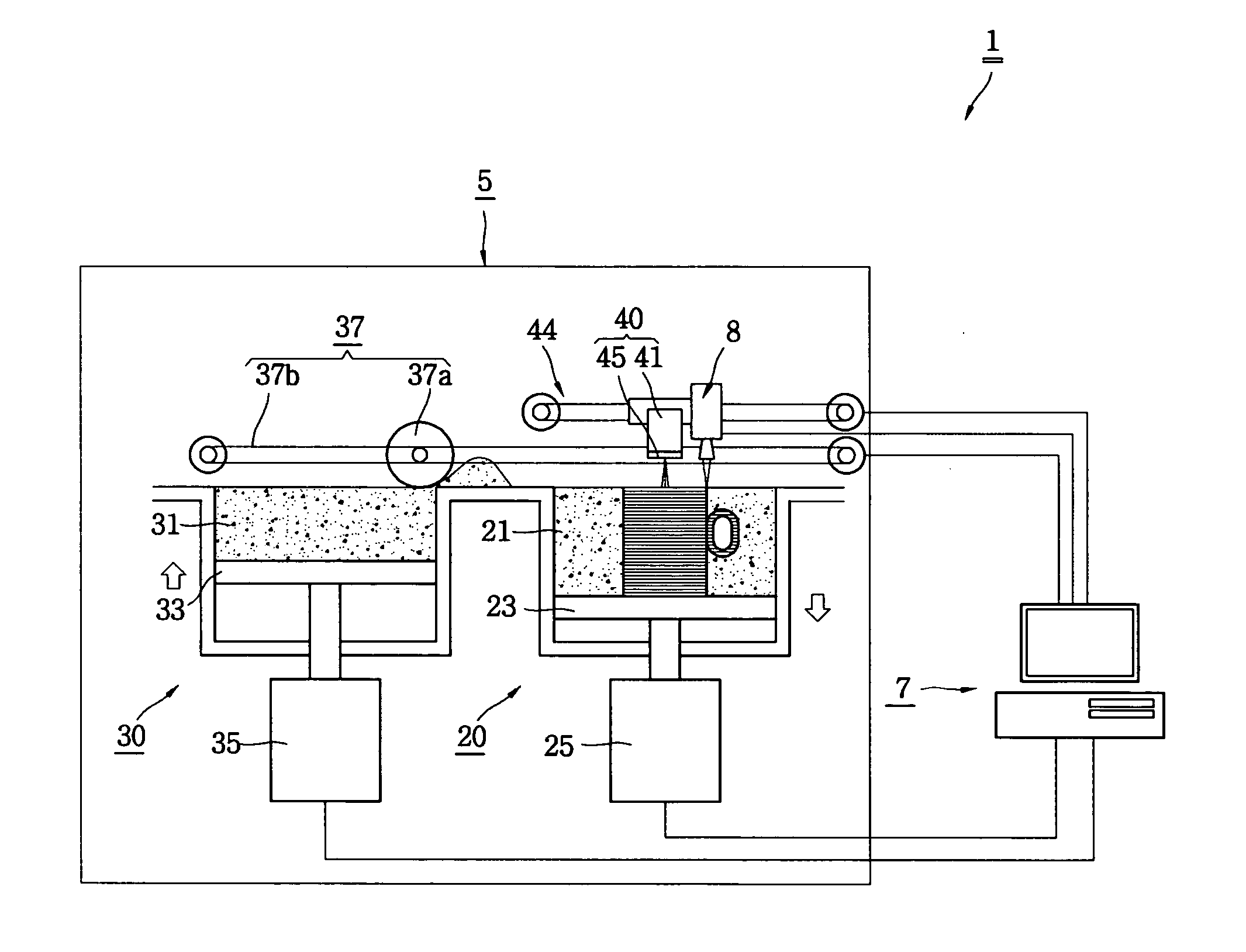
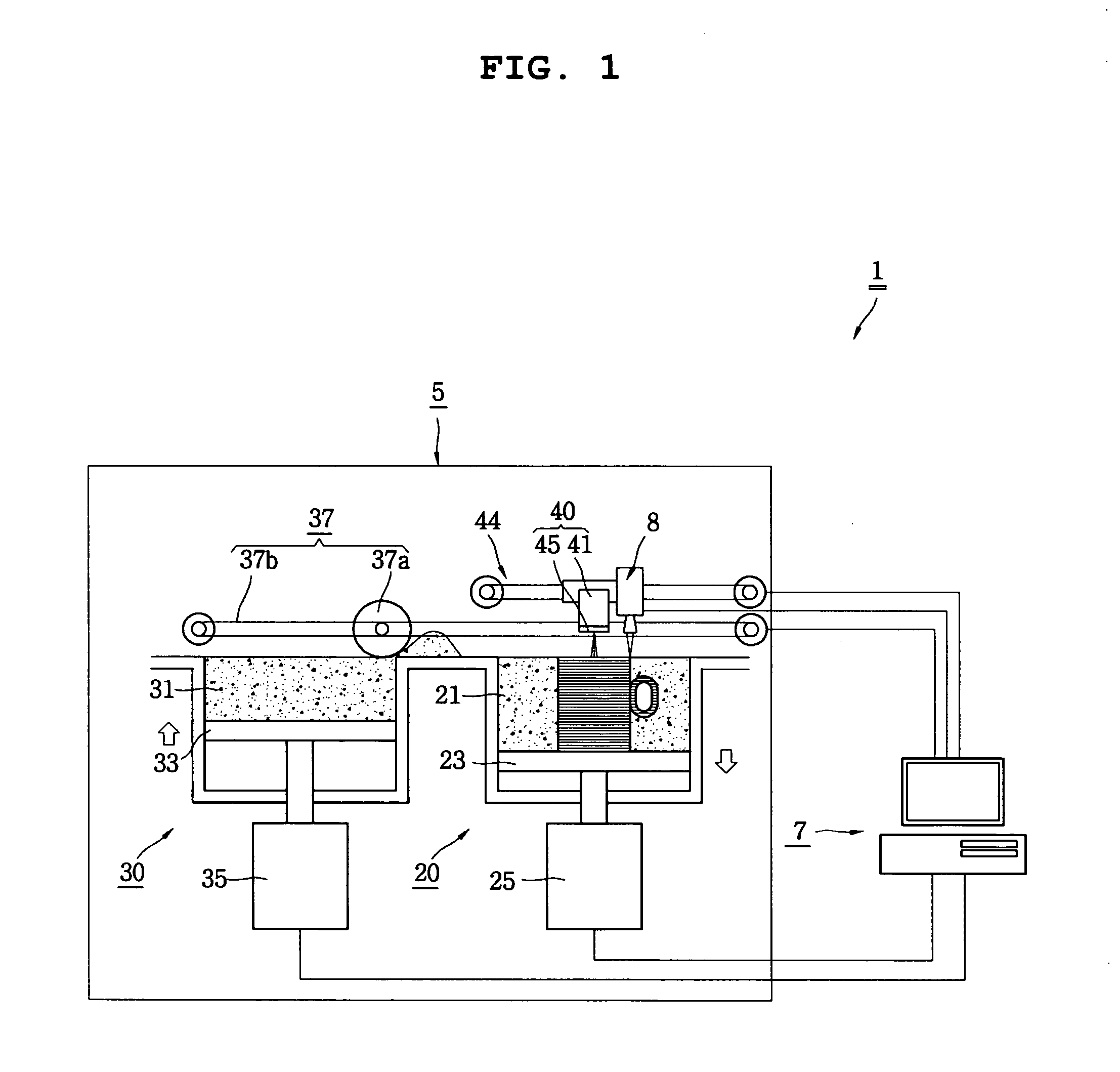
[0018]FIG. 1 is a schematic view of a three-dimensional printing prototyping system according to the present invention. As shown in the figure, the three-dimensional printing prototyping system 1 of the present invention includes a prototyping device 5 for prototyping a three-dimensional prototype, and a control computer 7 for controlling the operation of the prototyping device 5 and a curing device 8.

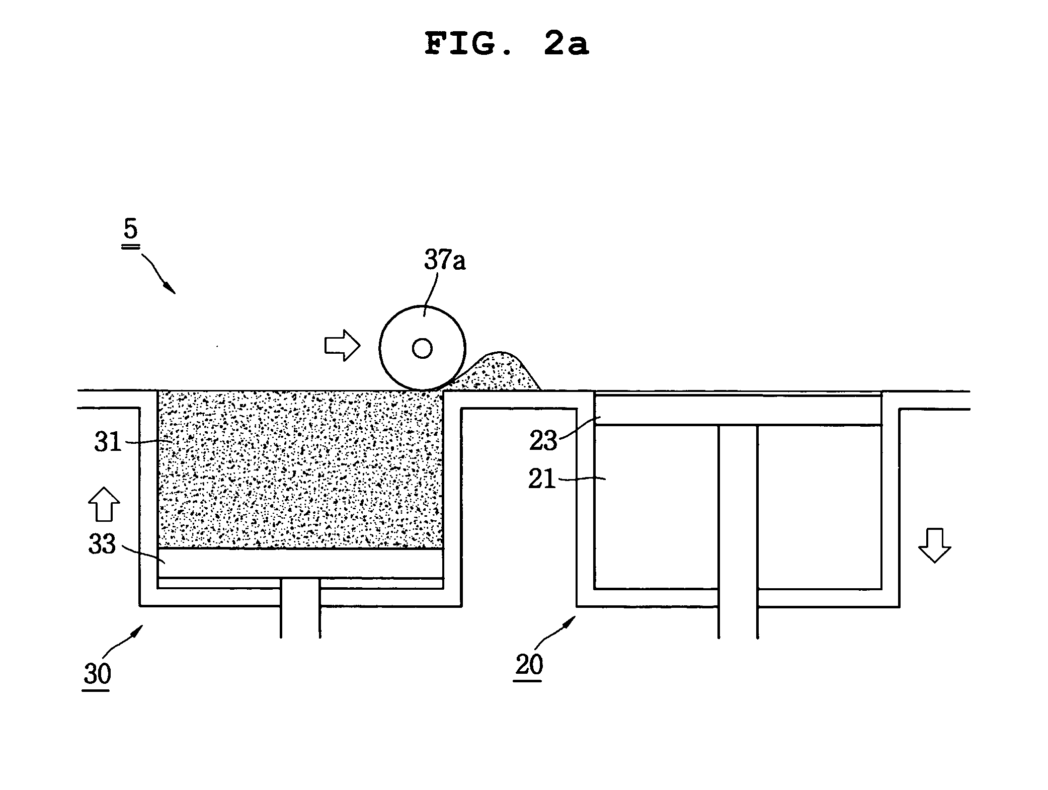
[0019] The prototyping device 5 includes a prototyping unit 20 in which a prototype is prototyped, a material supply unit 30 for supplying the prototyping unit 20 with a power material that corresponds to a prototyping material, a printing head 40 for injecting an adhesive material to a sectional region of the three-dimensional prototype made of the power material supplied to the prototyping unit 20, and the curing device 8 for curing a region to which the adhesive materi...


PUM

PropertyMeasurementUnit
thicknessaaaaaaaaaa
viscosityaaaaaaaaaa
areaaaaaaaaaaa

Abstract

The present invention relates to a three-dimensional printing prototyping system which includes a prototyping chamber having a prototyping table capable of moving up and down by a predetermined range, a material containing chamber containing a powder material and having a material supply table capable of moving up and down by a predetermined range, and a material supplying means for supplying the powder material contained in the material containing chamber to the prototyping table as much as a sectional thickness corresponding to divided section data of a three-dimensional prototype to be prototyped. The system of the present invention comprises a printing head for injecting a photocuring adhesive material to a region, corresponding to the sectional data, on the powder material supplied to the prototyping table; a curing device for photocuring at least the region on which the adhesive material is injected; and a control computer for controlling the printing head and the curing device such that the adhesive material is injected and cured, respectively, on the region corresponding to the divided section data of the three-dimensional prototype. According to the present invention, a period of time required in curing a three-dimensional prototype can be remarkably shortened and the three-dimensional prototype with its superior solidity can be obtained.

Description

BACKGROUND OF THE INVENTION [0001] 1. Field of the Invention [0002] The present invention relates to a three-dimensional printing prototyping system. [0003] 2. Description of the Related Art [0004] A three-dimensional printing prototyping system is a system for prototyping a three-dimensional prototype by using the ink-jet technique for use in an ink-jet printer. [0005] As shown in FIG. 5, a conventional three-dimensional printing prototyping system 101 is configured in such a manner that, when a powder material contained in a material containing chamber 131 is supplied to a prototyping table 123 in a prototyping chamber 121 as much as a predetermined sectional thickness by means of a roller 137 or the like, a printing head 140 injects an adhesive material onto a sectional layer corresponding to a three-dimensional prototype A′ to stack a relevant section, thereby finally prototyping the three-dimensional prototype A′. [0006] At this time, a binder is used as an adhesive material in...

Claims


Application Information

Patent Timeline
Patent Type & Authority Applications(United States)
IPC IPC(8): B29C35/08
CPCB29C67/0081B33Y30/00B29C64/165B29C35/02B32B37/12G06T17/00B33Y50/02
Inventor KIM, DONG SOOLEE, TAIK MINLEE, WON HEELIM, HYUN EUICHOI, BYUNG OH
Owner KOREA INST OF MACHINERY & MATERIALS
Learn More