Mold flash trap, process using and parts made thereby

a technology of mold flash and process, applied in the field of mold flash trap, can solve the problems of extreme precision required in the valve, system failure, unacceptable performance, etc., and achieve the effects of reducing the potential for forming flash, high-precision molded plastic, and reducing the formation of flash

Inactive Publication Date: 2006-05-11
ILLINOIS TOOL WORKS INC
View PDF11 Cites 7 Cited by
  • Summary
  • Abstract
  • Description
  • Claims
  • Application Information

AI Technical Summary

Benefits of technology

[0012] An advantage of the present invention is providing a mold to form highly precise molded plastic parts with substantially reduced potential for forming flash.
[0013] Another advantage of the present invention is providing a mold that reduces flash formation and thereby simplifies the manufacture of parts at lower cost by eliminating the need for extensive flash cleaning.
[0014] Still another advantage of the present invention is providing molded plastic parts that are highly precise and accurate with little or no flash for subsequent removal.
[0015] Other features and advantages of the invention will become apparent to those skilled in the art upon review of the following detailed description, claims and drawings in which like numerals are used to designate like features.

Problems solved by technology

The precision required in the valves is extreme, since openings are necessarily small and even a small variation can cause unacceptable performance.
Further, even extremely small contaminants can cause system failure by blocking the small ports or preventing valves from fully functioning between closed and opened positions.
A problem with known systems is that any leakage around the dump seat in the dump cartridge can adversely effect the operation of the brake system.
The result can be a long stopping distance or a soft brake pedal feel.
Because of the sensitivity of the dump seat, it is typical for the components to be highly machined metal parts, which results in the parts being relatively expensive.
However, the use of plastic is not without difficulties.
In known designs for such parts, the required precision of the dump seat makes molding difficult.
Wear and other conditions between the mold parts can also lead to flash.
While tolerable in some applications, the presence of flash in the dump seat of an anti-lock brake system valve is not acceptable.
The presence of flash can cause the valve to operate improperly and if the flash breaks loose and enters the brake fluid system, contamination can cause failure or unacceptable performance at numerous locations within the brake system.
With the openings or ports as small as they are, even a very small amount of flash can clog or cause failure.
Flash removal is difficult, even if separated from the part.
If flash is not completely removed from the part, subsequent system contamination can occur.

Method used


Image

  • Mold flash trap, process using and parts made thereby
  • Mold flash trap, process using and parts made thereby
  • Mold flash trap, process using and parts made thereby

Examples


Embodiment Construction

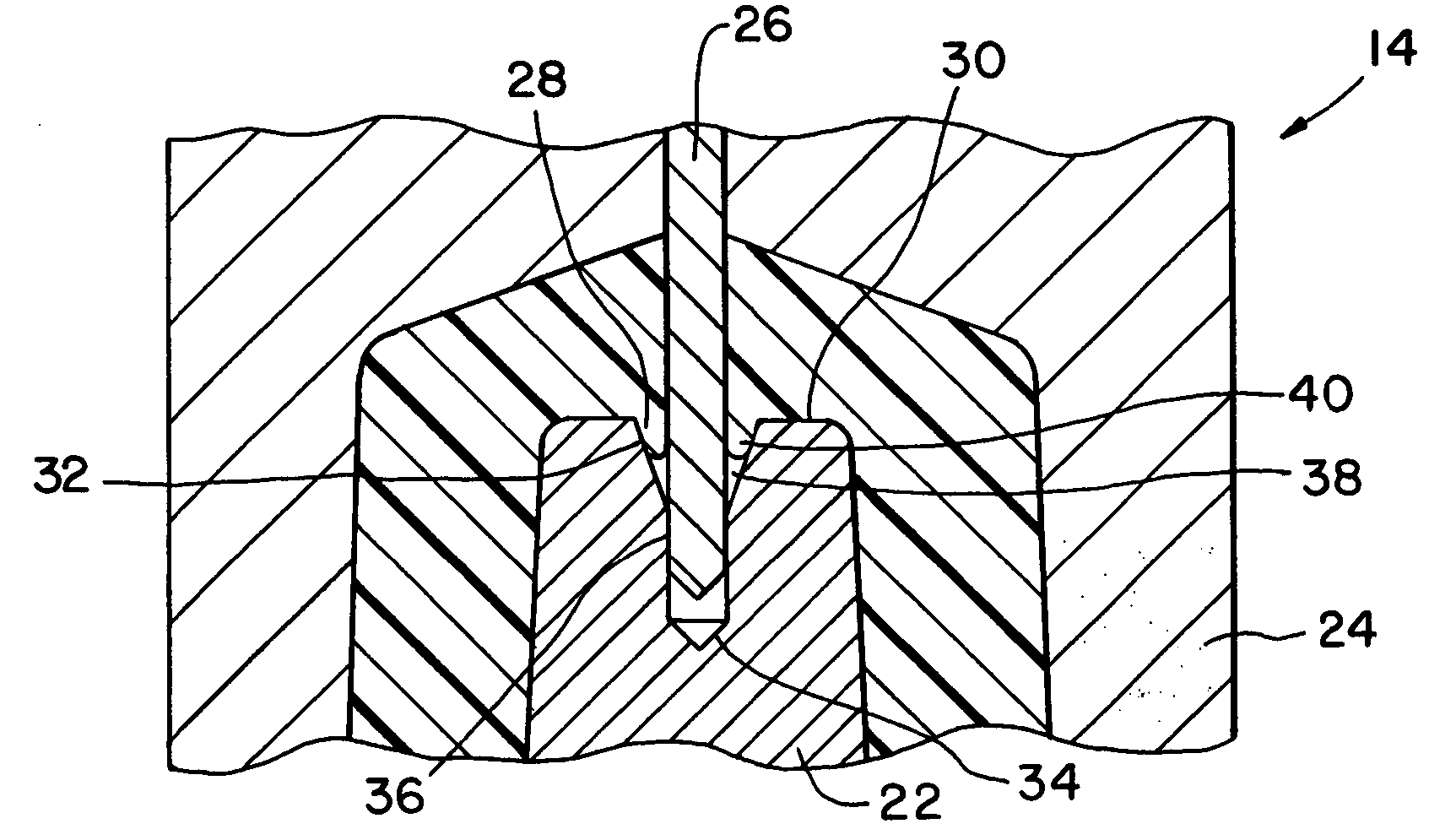
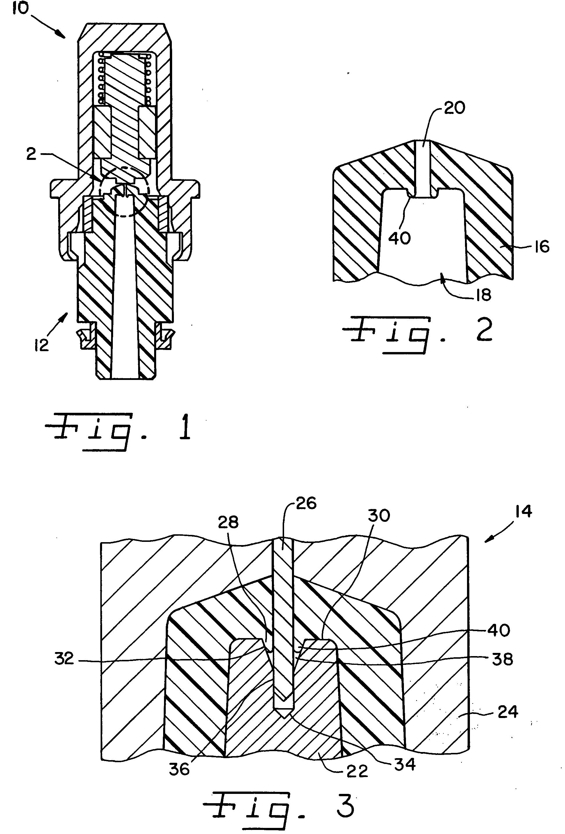
[0021] Referring now more specifically to the drawings and to FIG. 1 in particular, numeral 10 designates a valve having a molded part 12 in accordance with the present invention. Part 12 is formed in a mold 14 (FIG. 3) of the present invention. It should be understood that the present invention can be used for molding a variety of different parts including part 12 in valve 10. However, the present invention can also be used for forming parts other than parts for valves and can be used for forming parts of a variety of shapes, types and sizes. Further, the present invention can be utilized with a variety of plastics or other molded material for a variety of uses, purposes and applications. The invention can be used advantageously for producing many parts in which a reduction in the formation of flash is desirable.

[0022] Part 12 includes a body 16 defining an internal cavity 18 and an orifice or through hole 20 that is small in diameter and precise in specification. Orifice 20 exten...


PUM

PropertyMeasurementUnit
angleaaaaaaaaaa
widthaaaaaaaaaa
widthaaaaaaaaaa

Abstract

A mold for forming a part, a part formed in the mold and processes for using the mold and forming the part. The mold includes inner and outer mold pieces and a pin extending between the mold pieces to form the part having an internal cavity and an orifice extending into the cavity. The inner mold piece defines a pocket for receiving the pin. The pocket enables the formation of an annular donut-like projection around the orifice within the cavity.

Description

FIELD OF THE INVENTION [0001] The present invention relates generally to molded parts and, more particularly, the invention relates to highly precise parts for applications or installment in a system intolerant of contamination; and molds used for making such parts. BACKGROUND OF THE INVENTION [0002] In some applications, parts or components for which plastic is a suitable material have been made of more expensive metal because of the need for precision in the part in combination with the need for system cleanliness. For example, an anti-lock braking system on an automobile typically includes an isolation cartridge and a dump cartridge. Each controls the flow of brake fluid. During normal brake operation, when the brakes are applied the valve in the isolation cartridge opens to allow the brake system to operate the brakes. The valve in the dump cartridge is closed, not allowing any fluid to flow therethrough. When the anti-lock brake system is activated, the valve in the isolation c...

Claims


Application Information

Patent Timeline
Patent Type & Authority Applications(United States)
IPC IPC(8): B29C45/17
CPCB29C45/0025B29C45/2628
Inventor HAYES, MICHAEL S.SCHWAB, CHARLES M.FOLEY, PAUL C.
Owner ILLINOIS TOOL WORKS INC
Why Eureka
Try Eureka