Compact lancing device

a lancing device and compact technology, applied in the field of medical devices, can solve the problems of sound, vibration and noise of the lancing device, and large size of the lancing device, and achieve the effects of reducing vibration and noise, compact lancing device, and limiting the rotational movement of the lancet holder

Inactive Publication Date: 2006-05-11
LIFESCAN INC
View PDF19 Cites 129 Cited by
  • Summary
  • Abstract
  • Description
  • Claims
  • Application Information

AI Technical Summary

Benefits of technology

[0011] The concentric arrangement of the retraction spring and launch spring provide compactness to the compact lancing device. In addition, operative connections between the lancet holder and other c

Problems solved by technology

The arming and launching of conventional lancing devices involves a multitude of complicated mechanisms that result in the lancing device being relatively large in size, costly to manufacture and cumbe

Method used


Image

  • Compact lancing device
  • Compact lancing device
  • Compact lancing device

Examples


Embodiment Construction

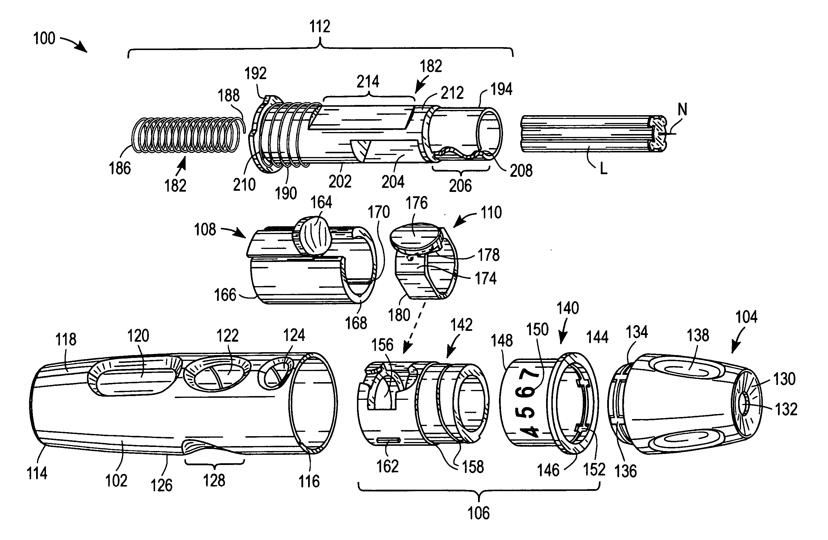
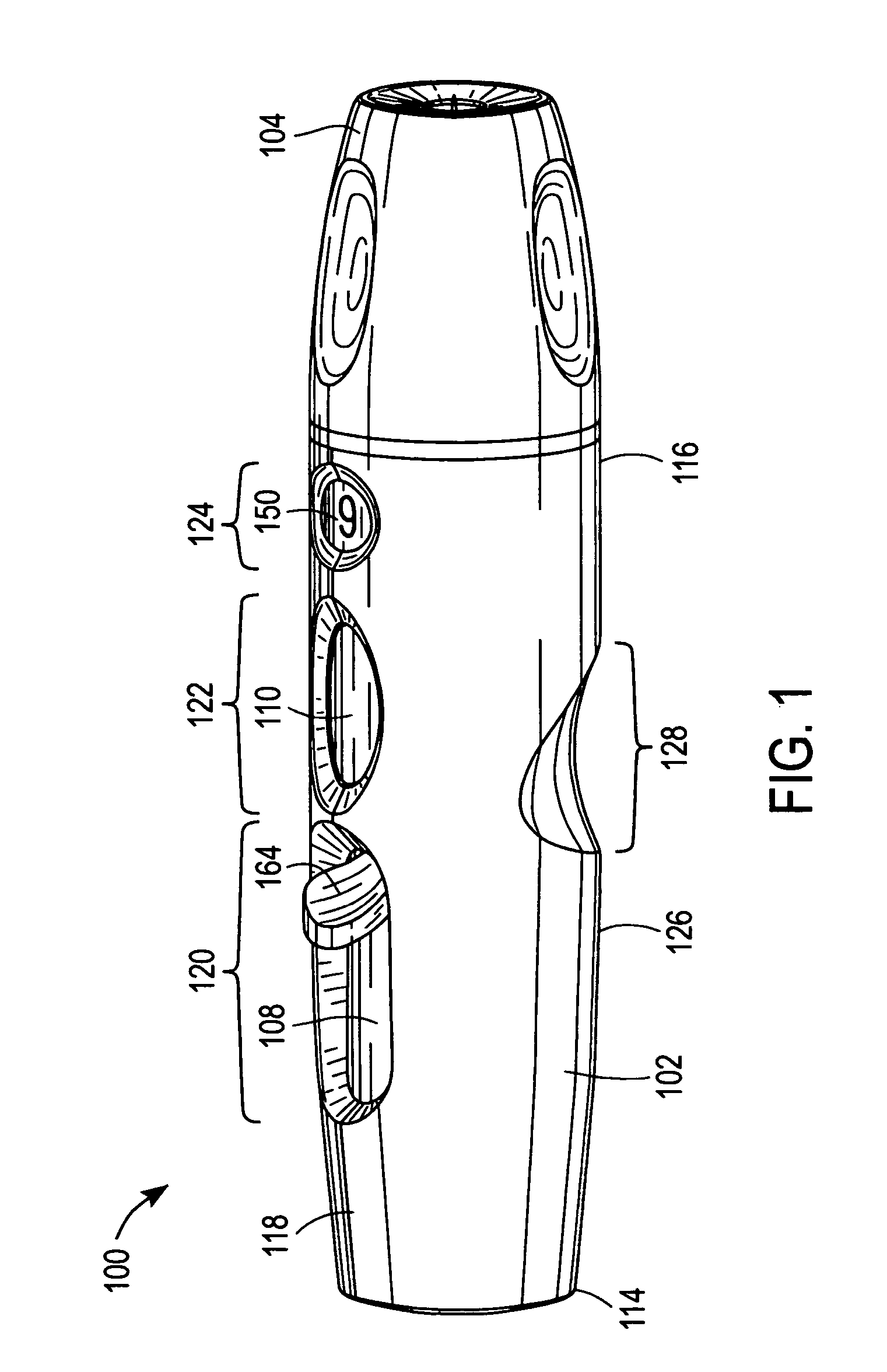
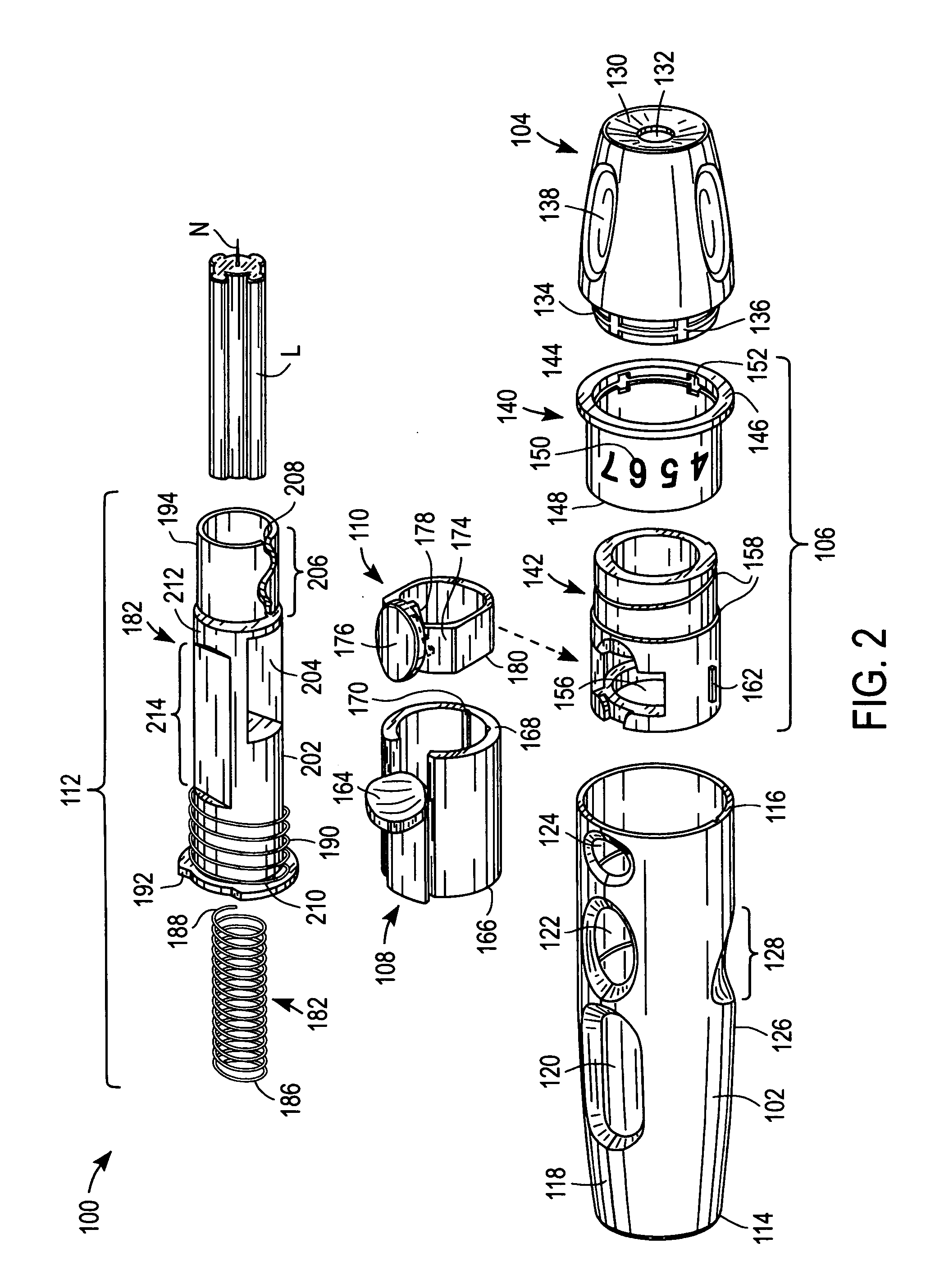
[0025]FIGS. 1, 2, 3, 4A, 4B, 5A, 5B and 6 are various depictions of a compact lancing device 100 according to an exemplary embodiment of the present invention. Compact lancing device 100 includes a housing 102, end cap 104, depth adjustment mechanism 106, arming mechanism 108, trigger mechanism 110, and launching mechanism 112.

[0026] As described in detail below, launching mechanism 112, arming mechanism 108 and trigger mechanism 110 are operatively connected such that a target site (e.g., a user's skin target site) can be lanced with a lancet (e.g., lancet L that includes lancet needle N) held within compact lancing device 100. In this regard, launching mechanism 112 is configured for launching lancet L such that lancet needle N lances a target site, arming mechanism 108 is configured for arming compact lancing device 100 prior to firing the compact lancing device (i.e., prior to launching lancet L), while trigger mechanism 110 is configured to actuate the firing of compact lancin...


PUM


Abstract

A compact lancing includes a housing, a moveable lancet holder disposed within the housing and configured to hold a lancet, a launching mechanism disposed within the housing, and arming and trigger mechanisms disposed at least partially within the housing. In addition, the launching mechanism includes a launch spring and a retraction spring. The lancet holder, launching mechanism, arming mechanism and trigger mechanism are operatively connected to lance a target site with a lancet held by the moveable lancet holder. In addition, the retraction spring is configured in an essentially concentric arrangement with the launch spring, thereby providing for compactness in design.

Description

BACKGROUND OF THE INVENTION [0001] 1. Field of the Invention [0002] The present invention relates, in general, to medical devices and, in particular, to lancing devices. [0003] 2. Description of the Related Art [0004] Conventional lancing devices generally have a rigid housing, various operating mechanisms and a lancet that can be armed and launched so as to briefly protrude from one end of the lancing device. For example, conventional lancing devices can include a lancet that is mounted within a rigid housing such that the lancet is movable relative to the rigid housing along a longitudinal axis thereof. Typically, the lancet is spring loaded and launched, upon release of the spring, to penetrate (i.e., “lance”) a target site (e.g., a dermal tissue target site). A bodily fluid sample (e.g., a whole blood sample) can then be expressed from the penetrated target site for collection and analysis. Conventional lancing devices are described in U.S. Pat. No. 5,730,753 to Morita, U.S. Pat...

Claims


Application Information

Patent Timeline
IPC IPC(8): A61B17/32
CPCA61B5/1411A61B17/32093A61B5/150022A61B5/150152A61B5/150183A61B5/150259A61B5/150358A61B5/150412A61B5/150503A61B5/150824A61B5/15113A61B5/15117A61B5/1513A61B5/1519A61B5/15194A61B5/157
Inventor OLSON, LORIN P.LEONG, KOON-WAH
Owner LIFESCAN INC
Why Eureka
Try Eureka