Optical proximity device for power tools

a technology of optical proximity and power tools, applied in the field of power tools, can solve the problems of considerable damage caused, the blade contact with the human hand is required to initiate the blade braking action,

Inactive Publication Date: 2006-05-18
BLACK & DECKER INC
View PDF7 Cites 100 Cited by
  • Summary
  • Abstract
  • Description
  • Claims
  • Application Information

AI Technical Summary

Problems solved by technology

The obvious disadvantage to this device is that blade contact with the human hand is required to initiate blade braking action.
Another disadvanta

Method used


Image

  • Optical proximity device for power tools
  • Optical proximity device for power tools
  • Optical proximity device for power tools

Examples


Embodiment Construction

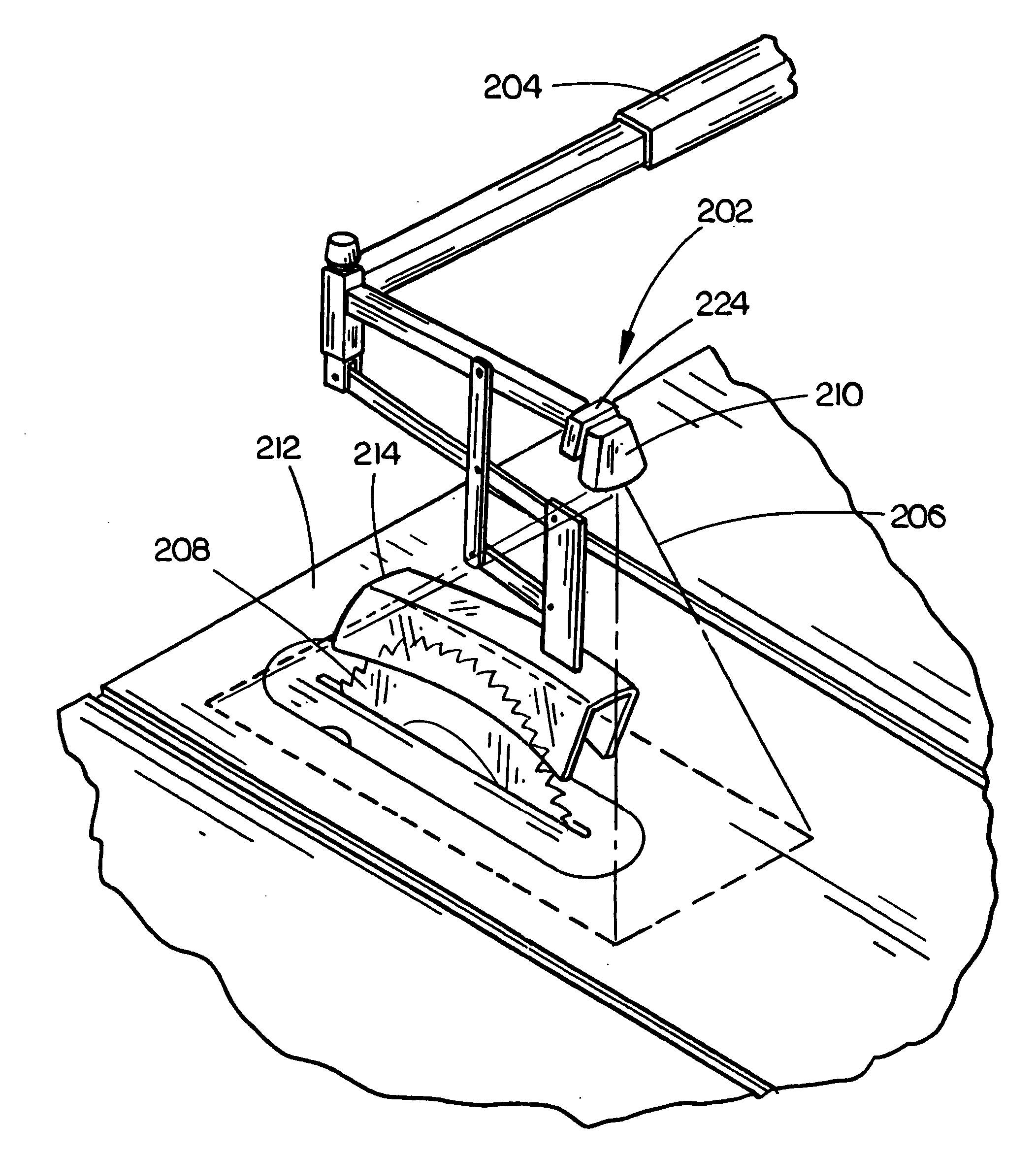
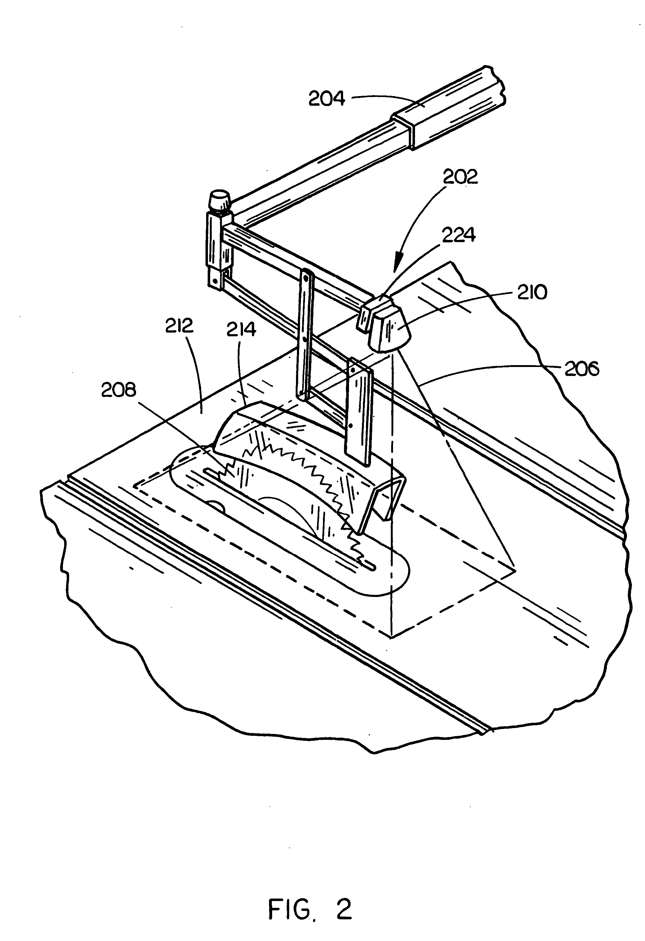
[0017] Those of skill in the art will appreciate that the apparatus of the present invention may be implemented with various power tools to prevent contact with an operating working element / to lockout a tool from use (prevent use). Those of skill in the art will appreciate that the optical proximity device in accordance with the present invention may be included on various power tools such as band saws, scroll saws, chop saws, miter saws, circular saws, panel cutters, planers, joiners, shapers, drill presses, grinders, drills, pneumatic fasteners, combustion fasteners, routers, cut-off tools, reciprocating saws, and the like.

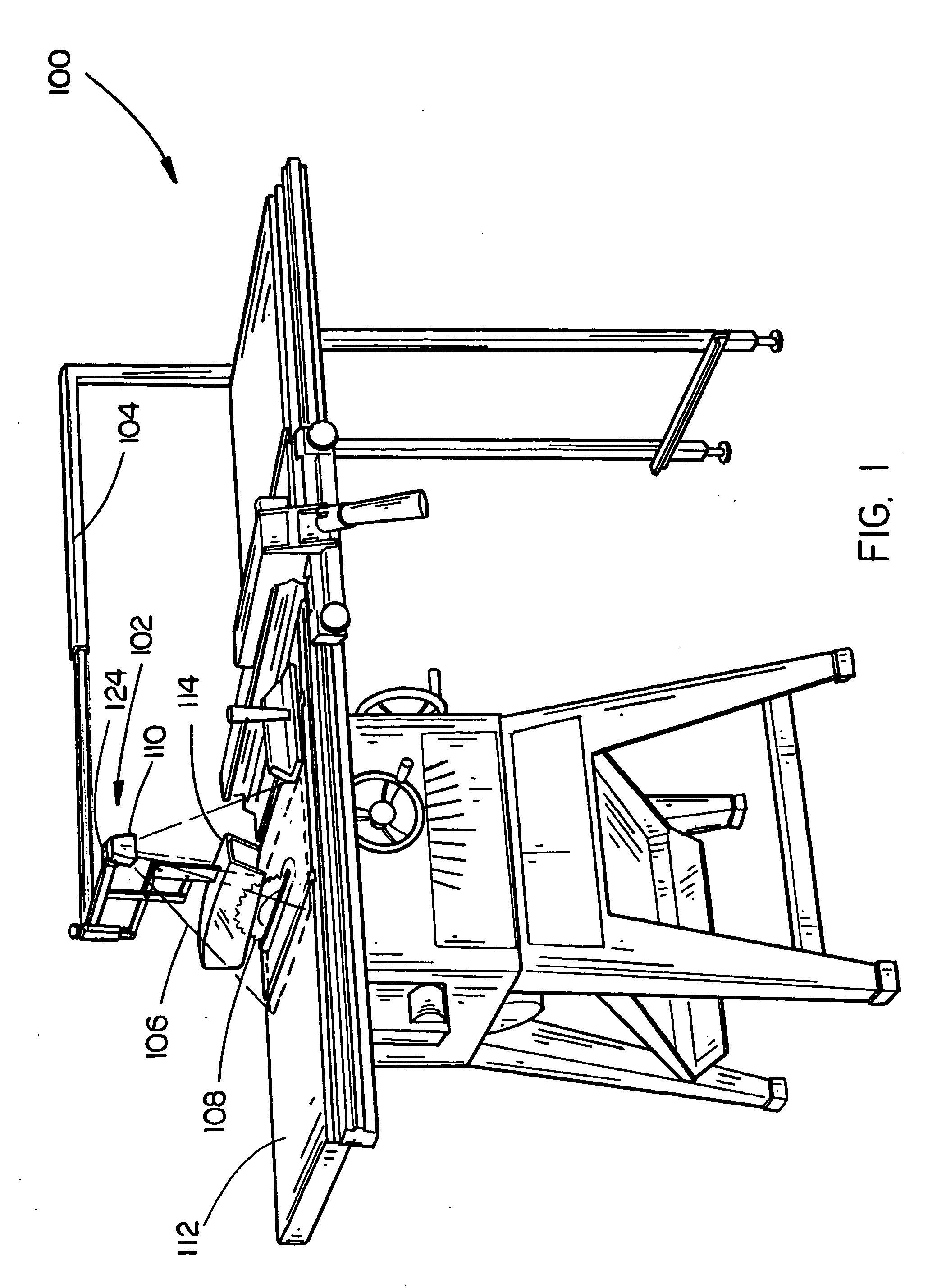
[0018] Referring to FIGS. 1 and 2 (wherein like numerals refer to like components), a table saw 100 in accordance with an aspect of the present invention is disclosed. In the present embodiment, an optical proximity device 102 is mounted to an over-arm type blade guard 104. In additional embodiments, an optical proximity device 102 may be positioned as desired ...


PUM

PropertyMeasurementUnit
Lightaaaaaaaaaa

Abstract

The present invention is directed to a power tool including a working element for performing a task. A light source is arranged to project a beam of light adjacent the working element. A detector, such as an electro-optic type detector, is communicatively coupled to the power tool such that the detector is capable of detecting the presence of a human body part in the beam of light. If a body part is detected, the detector may communicate to stop operation of the working element.

Description

CROSS REFERENCE [0001] The present application claims priority under 35 U.S.C. §119(e) to U.S. Provisional Patent Application Ser. No. 60 / 453,299, entitled: Optical Proximity Device for Power Tools, filed on Mar. 10, 2003, which is hereby incorporated by reference in its entirety.FIELD OF THE INVENTION [0002] The present invention generally relates to the field of power tools, and particularly to a device for preventing user contact with a working tool, such as a saw blade, included in a power tool. BACKGROUND OF THE INVENTION [0003] Traditionally, power tools have utilized mechanical guards to prevent the user from contacting working tool elements, such as saw blades, shaping knives, bits, and the like. Recently, power tools such as table saws have included systems for stopping the blade upon human contact. For example, a circular saw blade is statically charged, thus if the user contacts the blade the resultant discharge is utilized to initiate a stopping procedure. The obvious di...

Claims


Application Information

Patent Timeline
IPC IPC(8): B26D5/00
CPCB23D59/001B27G21/00B23Q17/2438F16P3/144B23Q11/0082F16P3/14Y10T83/081
Inventor SMITH, MATTHEW A.KELLER, DAVID V.GARCIA, JAIME E.WESTON, JEFFREY D.
Owner BLACK & DECKER INC
Why Eureka
Try Eureka