Pressure washer

a technology for pressure washers and washers, applied in the direction of cleaning processes and utensils, chemistry apparatus and processes, cleaning using liquids, etc., can solve the problems of increasing manufacturing time, complex mounting structure, and increasing the cost of providing axle assemblies and protecting covers, so as to prevent damage

Inactive Publication Date: 2006-05-18
BLACK & DECKER INC
View PDF11 Cites 27 Cited by
  • Summary
  • Abstract
  • Description
  • Claims
  • Application Information

AI Technical Summary

Benefits of technology

[0008] In an aspect of the invention, a pressure washer is disclosed. In accordance with the present aspect, a pressure washer includes an engine for mechanically coupled to a pump. An internal mounting assembly including a folded portion is disposed generally between the engine and the pump so as to mount / support the engine and pump structure. In alternative embodiments, a unitary axle bracket, a separate axle bracket, or the like is integrated with a folded main mounting. An axle assembly having at least two spaced apart wheels pivotally mounted to an axle which extends through the internal mounting axle bracket is included in the pressure washer. A generally U-shaped frame member is secured to at least one of the internal mounting / engine. The U-shaped frame member being configured to support the pressure washer in a tripod like fashion with the wheels when disposed on a level support surface. A plastic outer housing is configured so as to substantially encompass the pump so as to prevent damage and the like.

Problems solved by technology

The difficulties associated with manufacturing these frames include the complexity of the mounting structure, the expense of providing an axle assembly and the configuration of the protecting coverings.
The preceding considerations may significantly increase manufacturing time and increase component expense.
These procedures increase expense.

Method used


Image

  • Pressure washer
  • Pressure washer
  • Pressure washer

Examples


Embodiment Construction

[0017] Reference will now be made in detail to the presently preferred embodiments of the invention, examples of which are illustrated in the accompanying drawings. It is to be appreciated that corresponding reference numbers refer to corresponding structures.

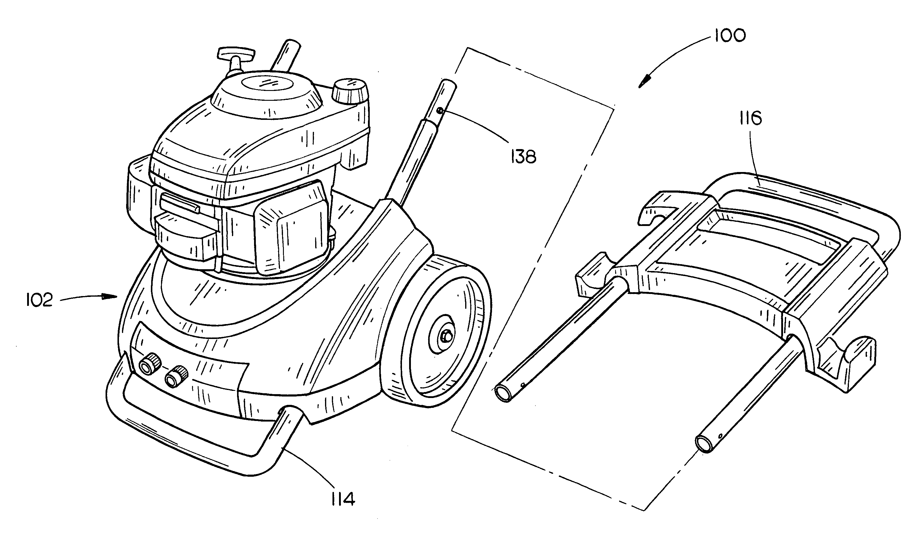
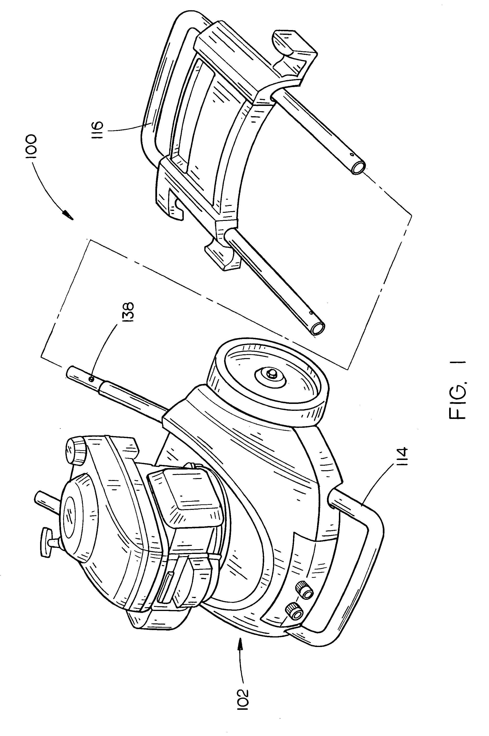
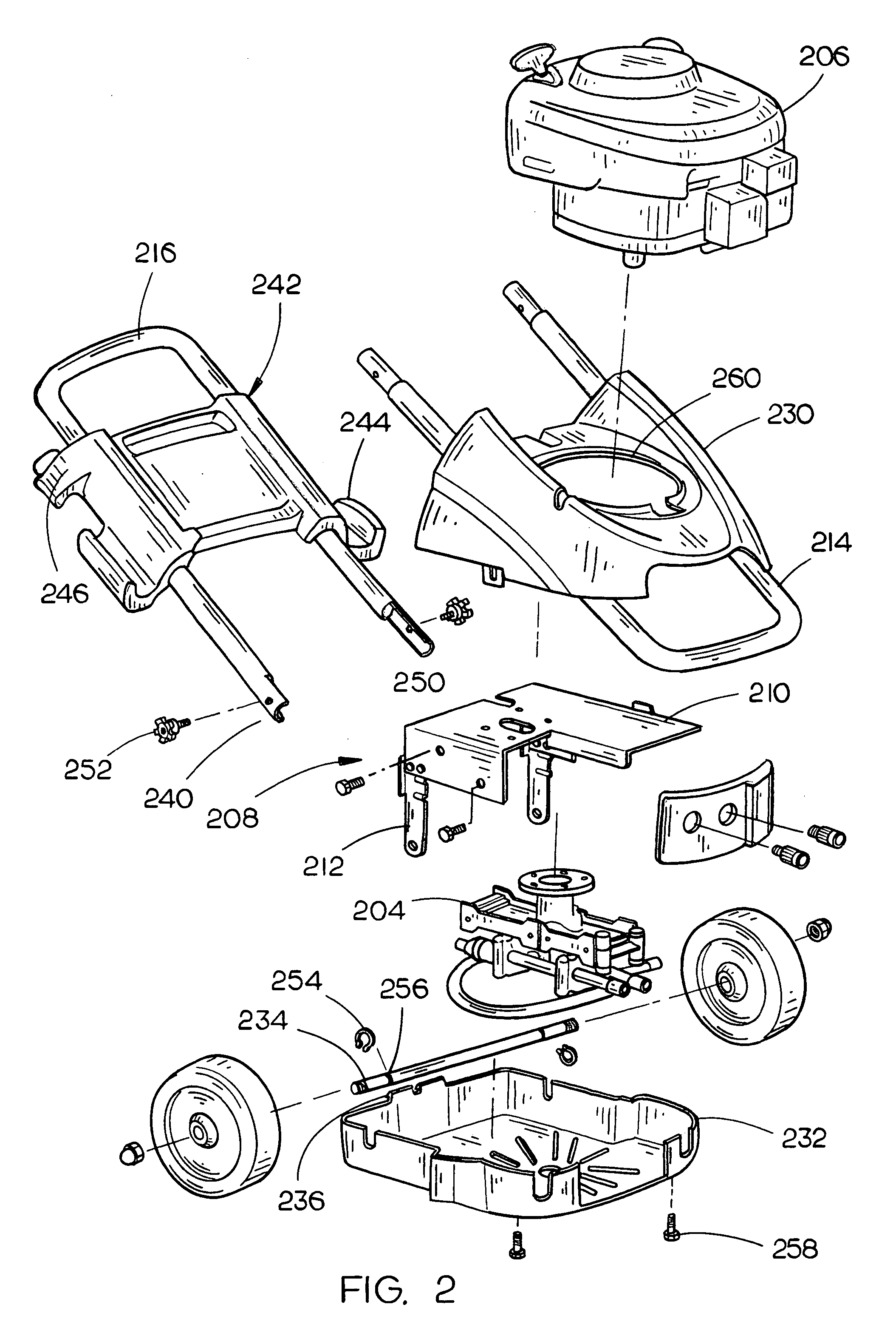
[0018] Referring to FIGS. 1 and 2, a pressure washer 100 in accordance with an aspect of the present invention is discussed. In the present embodiment, the pressure washer 100 includes a plastic outer housing 102 for substantially encompassing various washer components such as a pump 204 for pressurizing fluid from a first lower pressure to a higher pressure. In the present embodiment, the pressure washer is a vertical washer wherein the pump is disposed generally below an engine 206, as generally orientated in FIG. 1. The pressure washer 200 implements an internal mounting assembly 208 for providing a mounting for various pressure washer components such as the engine, pump and the like. In the current embodiment, the internal...


PUM


Abstract

The present invention is directed to a pressure washer having an internal mounting and outer clam shell housing. Accordingly, a pressure washer includes an engine for mechanically coupled to a pump. An internal mounting assembly including a folded portion is disposed generally between the engine and the pump so as to mount / support the engine and pump structure. In embodiments, various axle mounting structures such as a unitary axle bracket, a separate axle bracket, or the like is integrated with a folded main mounting into the mounting assembly. An axle assembly having at least two spaced apart wheels pivotally mounted to an axle which extends through the internal mounting axle bracket is included in the pressure washer. A generally U-shaped frame member is secured to at least one of the internal mounting / engine. The U-shaped frame member is implemented to support the pressure washer in a tripod like fashion with the wheels when disposed on a support surface. A plastic outer housing is utilized to substantially encompass the pump so as to prevent damage, minimize the need for refinement of the internal mounting assembly (for ascetics, for corrosion protection, finishing), and the like. Preferably, the outer housing implements clam shell portions with corresponding mechanical interconnects to mechanically secure the various sections. A fastener may be implemented to secure the shell portions generally adjacent a side opposite the mechanical interconnects.

Description

CROSS REFERENCE [0001] The present application claims priority under 35 U.S.C. §119(e) to U.S. Provisional Patent Ser. No. 60 / 525,526, entitled: Pressure Washer, filed on Nov. 26, 2003, which is hereby incorporated in its entirety.FIELD OF THE INVENTION [0002] The present invention relates to the field of power tools and particularly to a mounting and frame configuration for a power washer. BACKGROUND OF THE INVENTION [0003] Typically, portable engine powered devices such as generators, power washers compressors, power paint sprayers and the like are mounted on frame structures for transport between work sites. The difficulties associated with manufacturing these frames include the complexity of the mounting structure, the expense of providing an axle assembly and the configuration of the protecting coverings. The preceding considerations may significantly increase manufacturing time and increase component expense. [0004] For instance, pressure or power washers typically are either ...

Claims


Application Information

Patent Timeline
Patent Type & Authority Applications(United States)
IPC IPC(8): B08B3/12
CPCB08B3/026B08B2203/0211
Inventor LEASURE, JEREMY D.REEVES, KIM C.ANDERSON, RANDY
Owner BLACK & DECKER INC
Why Eureka
Try Eureka