Wall-mounted shelving system

a shelving system and wall-mounted technology, applied in the field of storage systems, can solve the problems of limiting the shelf length to the spacing, attaching the system to the wall, and limited the location at which such a system can be mounted, and achieve the effects of convenient cleaning, convenient installation, and strong practicability

Inactive Publication Date: 2006-05-18
INTERMETRO IND CORP
View PDF25 Cites 16 Cited by
  • Summary
  • Abstract
  • Description
  • Claims
  • Application Information

AI Technical Summary

Benefits of technology

[0014] It is an object of the present invention to provide a simplified wall-mounted shelving system that offers advantages over prior art systems. In particular, it is an object of the pre

Problems solved by technology

Although these known systems have utility in many applications, they suffer from a number of drawbacks.
One common problem with such systems relates to their attachment to a wall.
For example, in the case of the systems designed for use with typical stud-wall construction, there can be difficulties in attaching the system to the wall such that the system will be capable of supporting substantial weight.
However, attaching the uprights of such system directly to the studs, as suggested above, makes the installation dependent on stud spacing, which can then constrain the shelf length to that spacing.
Therefore, the location at which such a system can be mounted is limited.
However, a common problem with the resulting installation is that it is often unattractive.
Further, such installation can involve additional cost and effort, and lacks flexibility, because the uprights are typically secured to the horizontal strip using convention fasteners like screws.
Another common problem with known wall systems relates to the actual task of attaching them to a wall.
It can be difficult to arr

Method used


Image

  • Wall-mounted shelving system
  • Wall-mounted shelving system
  • Wall-mounted shelving system

Examples


Embodiment Construction

[0043] The present invention will now be described with reference with certain exemplary embodiments. However, it should be understood by those skilled in the art that various modifications can be made to the described embodiments without departing from the spirit or scope of the present invention or the concluding claims. Moreover, it is to be understood that terms such as “upper”, “lower”, “upwardly”, “downwardly”, “top” and “bottom” are used in this specification and the concluding claims to refer to orientations of and locations on various components as if they are in their installed states.

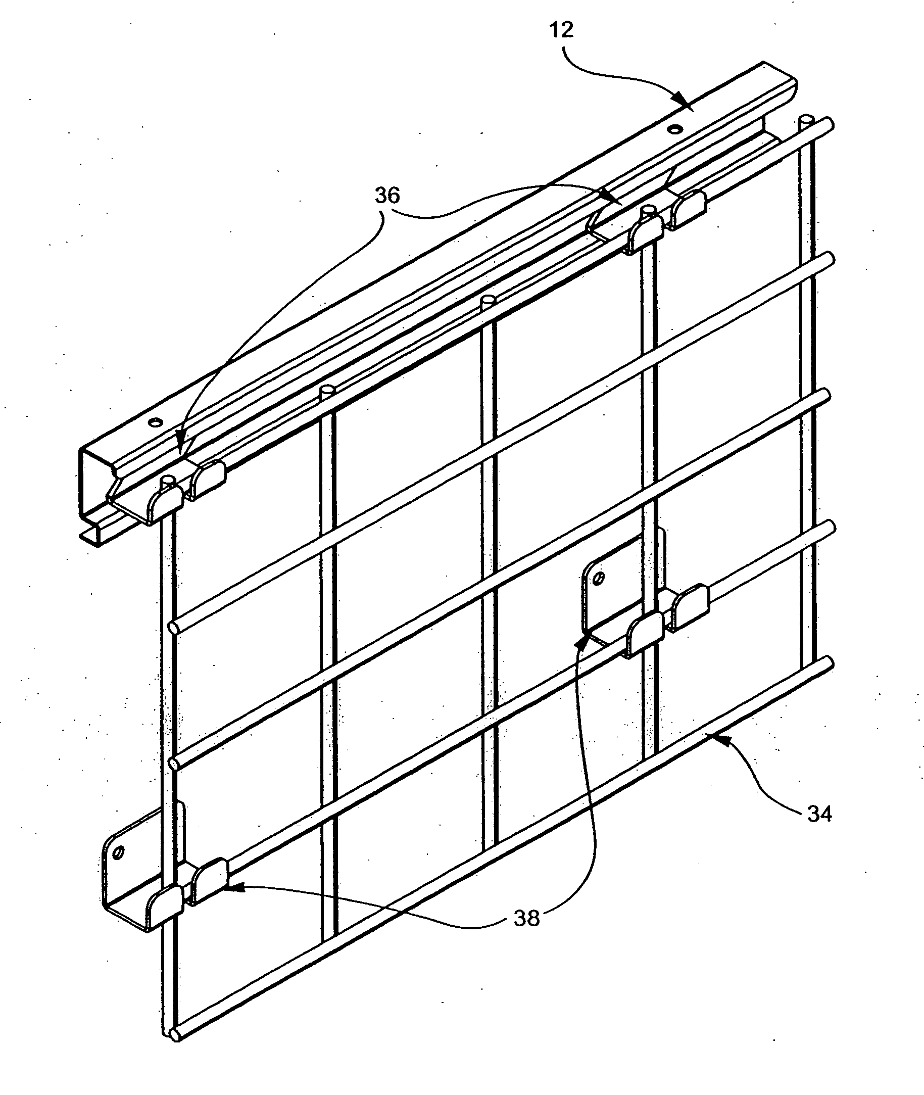
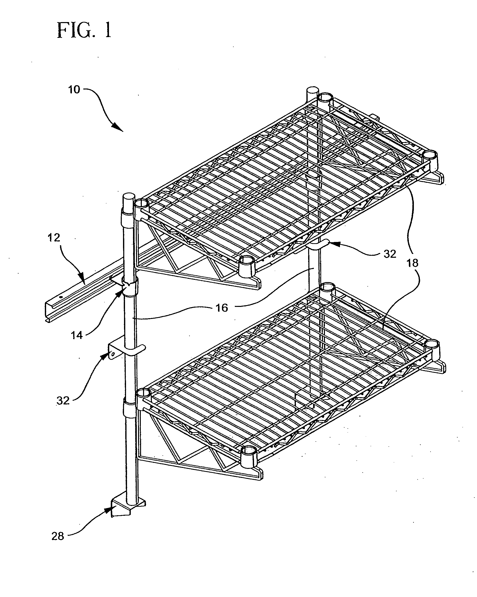
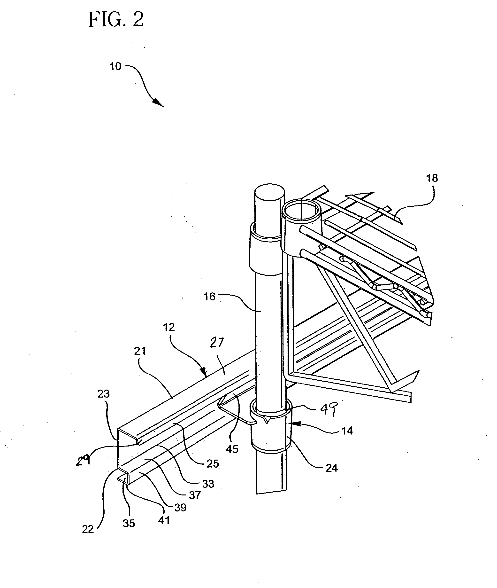
[0044] In a preferred embodiment of the present invention, a wall-mounted shelving system is provided that incorporates unique hardware that constitutes a substantial improvement over the known prior art. This hardware desirably makes use of the fundamental principles of the Maslow Patents cited above in a new and different way, but may also be adapted to other configurations. In the preferr...


PUM


Abstract

A wall-mounted shelving system is provided that is easy to install, allows for a placement which is unlimited by stud location, holds heavy loads, and is easily cleanable. This wall-mounted shelving system includes a track and a bracket engagable with the track. The bracket has a collar for supporting a shelf-carrying pilaster and an engaging element protruding from the collar that includes a floor and an arm projecting upwardly from the floor to define an elbow. The track is adapted to be mounted horizontally on a wall and includes a downwardly open channel at its top and an outwardly projecting ledge at its bottom. The upper extreme of the engaging element arm is received in the channel of the track while the elbow can be supported to rest on the ledge. A pilaster is adapted to then be supported in the collar through an intermediate wedge member, and shelves and other objects can be supported on the pilaster.

Description

CROSS-REFERENCE TO RELATED APPLICATION [0001] This application claims the benefit of U.S. Provisional Patent Application No. 60 / 625,407, filed Nov. 3, 2004, which is incorporated herein by reference.BACKGROUND OF THE INVENTION [0002] 1. Field of the Invention [0003] This invention relates generally to the field of storage systems and more particularly to an improved wall-mounted shelving system in which one or more shelves can be easily mounted in cantilevered fashion to a wall using certain unique hardware. The unique hardware used in the wall-mounted shelving system of the present invention includes a mounting bracket that has an inverted frustoconical collar which receives a sleeve having a mating frustoconical outer surface and a cylindrical inner surface. The sleeve, in turn, embraces a pilaster in the form of a post. The bracket further includes an engaging member protruding from the collar, which is formed to engage a track mounted horizontally on a wall. Two or more posts ma...

Claims


Application Information

Patent Timeline
IPC IPC(8): A47G29/02E06B7/28
CPCA47B55/02A47B96/067
Inventor SWARTZ, ROBERT K.DROPPERS, KENTON J.WELCH, ROBERT J.JANICK, JAMES J.OLSON, JEFFREY C.STEELE, ROBERT R.
Owner INTERMETRO IND CORP
Why Eureka
Try Eureka