Method and system for selectively charging a battery

a battery and selective charging technology, applied in the direction of charging/discharging, charging maintainance, electric vehicles, etc., can solve the problems of inefficient charging of batteries, dangerous situations, etc., and achieve the effect of reducing the charging voltage, and minimizing the power dissipation in the battery

Inactive Publication Date: 2006-05-18
MOTOROLA INC
View PDF4 Cites 91 Cited by
  • Summary
  • Abstract
  • Description
  • Claims
  • Application Information

AI Technical Summary

Benefits of technology

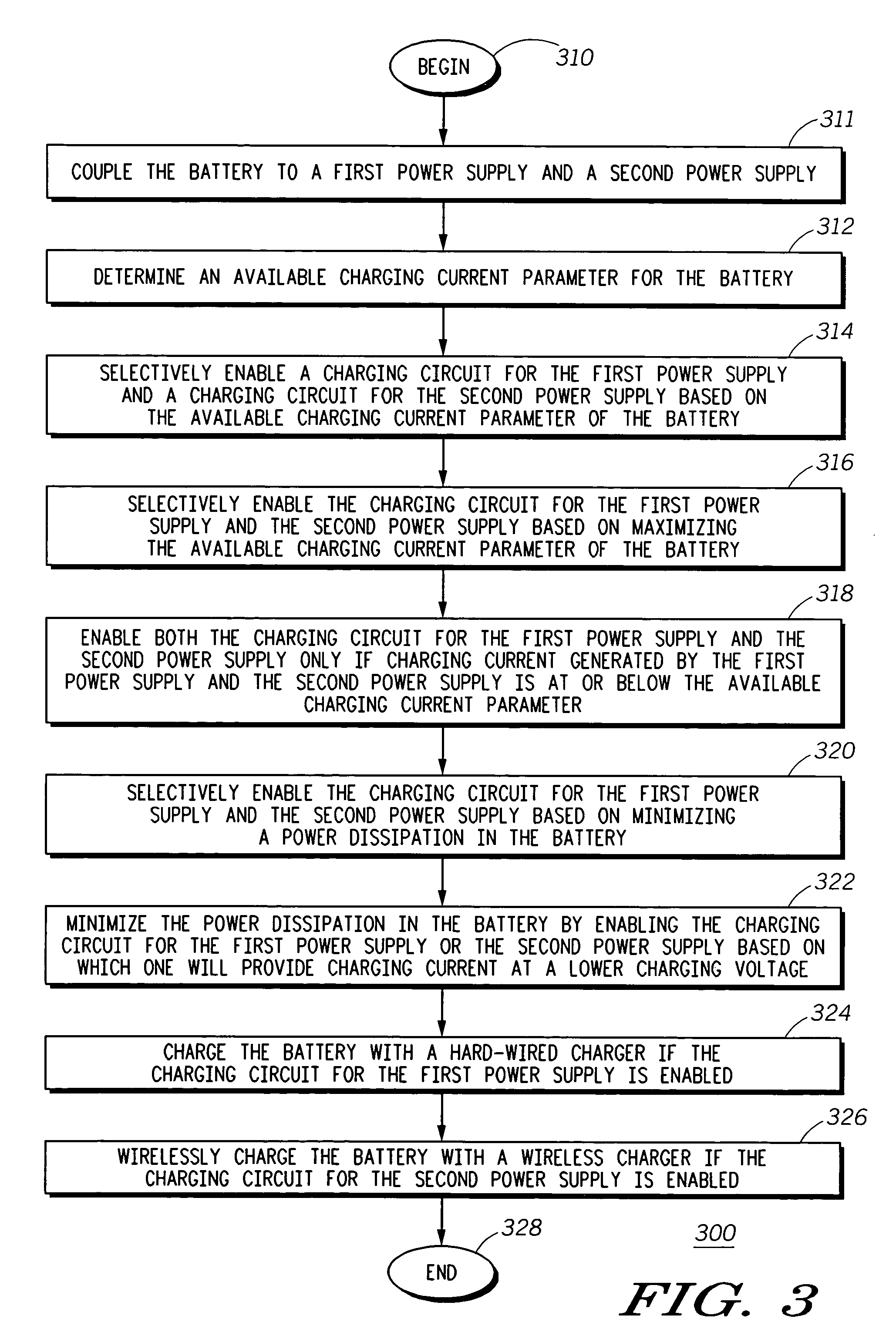
[0006] The present invention concerns a method for selectively charging a battery. The method can include the steps of coupling the battery to a first power supply, coupling the battery to a second power supply, determining an available charging current parameter for the battery and selectively enabling a charging circuit for the first power supply and a charging circuit for the second power supply based on the available charging current parameter of the battery. In one arrangement, the selectively enabling step can further include selectively enabling the charging circuit for the first power supply and the charging circuit for the second power supply based on maximizing the available charging current parameter of the battery. In another arrangement, the selectively enabling step can further include enabling both the charging circuit for the first power supply and the charging circuit for the second power supply only if charging current generated by the first power supply and the second power supply is at or below the available charging current parameter.
[0007] Also, the selectively enabling step can further include selectively enabling the charging circuit for the first power supply and the charging circuit for the second power supply based on minimizing a power dissipation in the battery. In yet another arrangement, the selectively enabling step can further include minimizing the power dissipation in the battery by enabling at least one of the charging circuit for the first power supply and the charging circuit for the second power supply based on which of the first power supply and the second power supply will provide charging current at a lower charging voltage.

Problems solved by technology

This prioritization process is done to prevent the battery from being overcharged, which can lead to a dangerous situation.
While the current design improves safety, it nonetheless presents an inefficient way to charge batteries.

Method used


Image

  • Method and system for selectively charging a battery
  • Method and system for selectively charging a battery
  • Method and system for selectively charging a battery

Examples


Embodiment Construction

[0016] While the specification concludes with claims defining the features of the invention that are regarded as novel, it is believed that the invention will be better understood from a consideration of the following description in conjunction with the drawing figures, in which like reference numerals are carried forward.

[0017] As required, detailed embodiments of the present invention are disclosed herein; however, it is to be understood that the disclosed embodiments are merely exemplary of the invention, which can be embodied in various forms. Therefore, specific structural and functional details disclosed herein are not to be interpreted as limiting, but merely as a basis for the claims and as a representative basis for teaching one skilled in the art to variously employ the present invention in virtually any appropriately detailed structure. Further, the terms and phrases used herein are not intended to be limiting but rather to provide an understandable description of the in...


PUM


Abstract

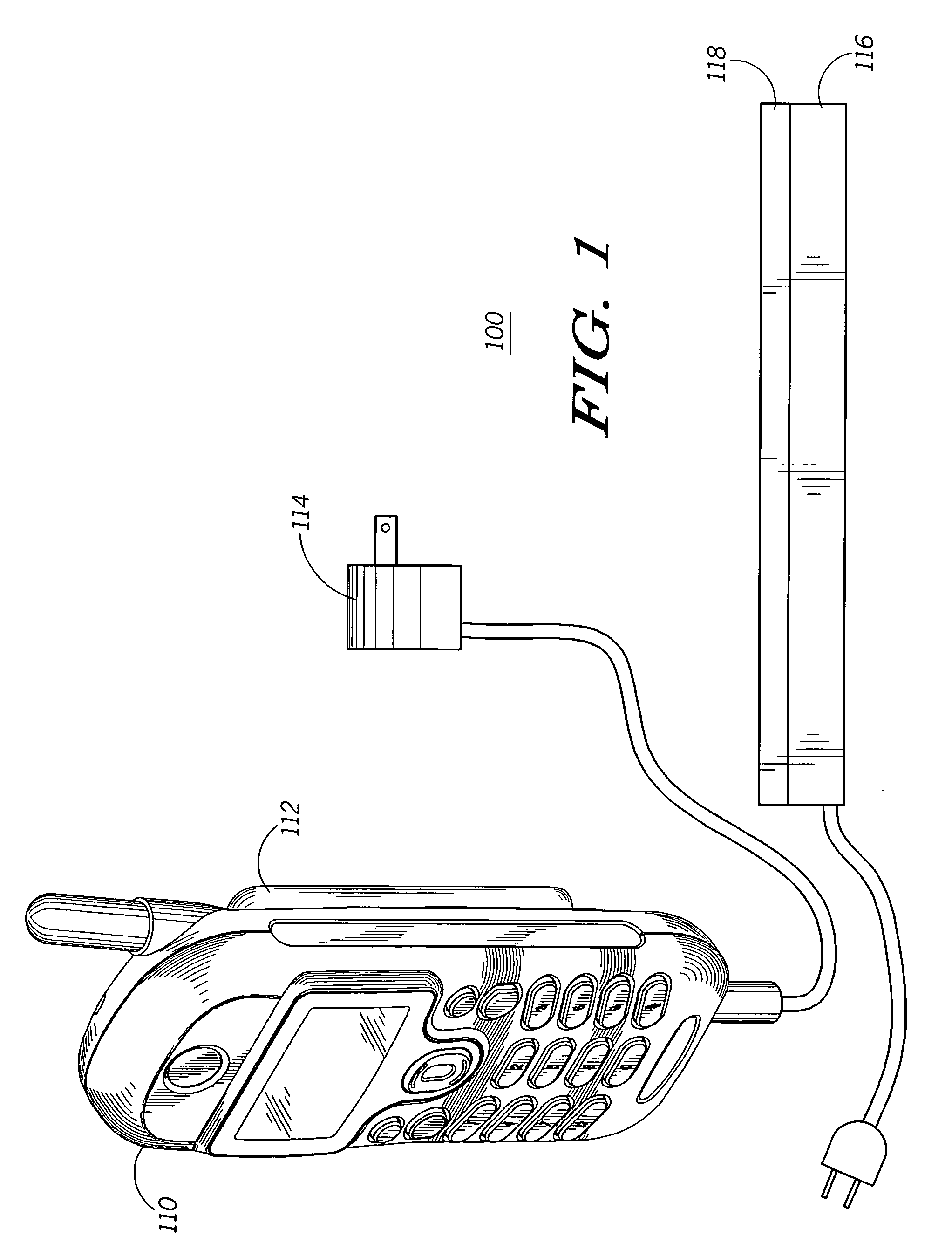
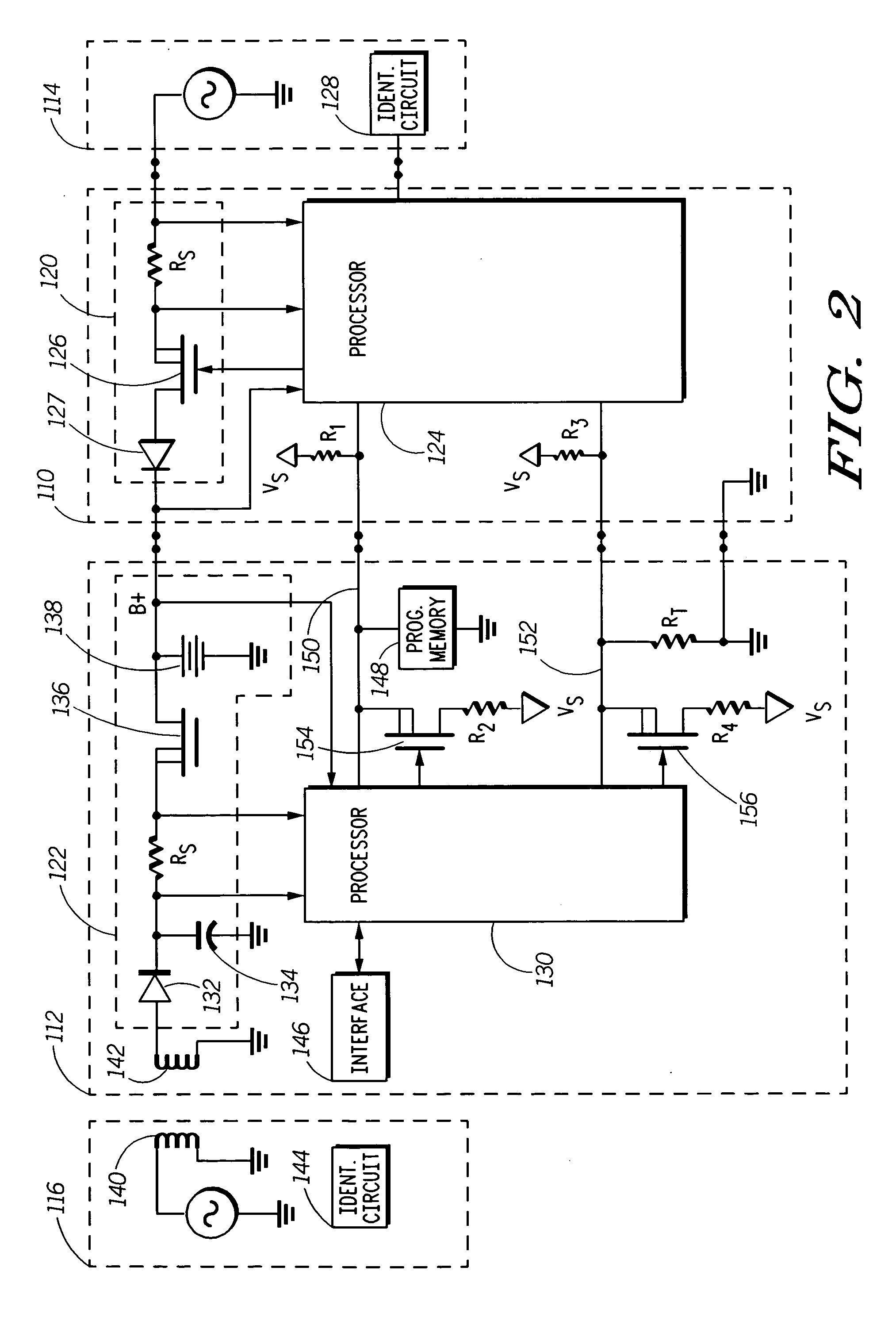
The invention concerns a method (300) and system (100) for selectively charging a battery (112). In one arrangement, the method can include the steps of coupling (311) the battery to a first power supply (114), coupling (311) the battery to a second power supply (116), determining (312) an available charging current parameter for the battery and selectively enabling (314) a charging circuit (120) for the first power supply and a charging circuit (122) for the second power supply based on the available charging current parameter of the battery. The selectively enabling process can be based on maximizing (316) an available charging current of the battery and minimizing (320) a power dissipation of the battery. As an example, the first power supply can be a hard-wired charger (114), and the second power supply can be a wireless charger (116).

Description

BACKGROUND OF THE INVENTION [0001] 1. Field of the Invention [0002] This invention relates in general to methods for charging batteries and more particularly to methods for charging batteries through conventional and wireless chargers. [0003] 2. Description of the Related Art [0004] Portable electronic devices have become ubiquitous in today's society. These devices are generally powered by one or more rechargeable batteries. For example, most cellular telephones can be coupled to a charger that can charge the telephone's battery after several hours, depending on how badly the battery is depleted. Consumers have many different types of chargers to choose from, including chargers that are physically coupled to the cellular telephone and wireless chargers. The chargers that are physically coupled to the cellular telephone may be referred to as standard or conventional chargers. Wireless chargers generally include a plate for receiving the device to be charged. [0005] In view of these ...

Claims


Application Information

Patent Timeline
Patent Type & Authority Applications(United States)
IPC IPC(8): H02J7/00
CPCH02J7/0057H02J7/025H02J50/10H02J7/0069
Inventor PATINO, JOSEPHDEMURO, DAVID M.
Owner MOTOROLA INC
Why Eureka
Try Eureka