On-the-fly introduction of inter-channel delay in a pulse-width-modulation amplifier

a technology of pulse width modulation and inter-channel delay, which is applied in the field of audio amplifiers, can solve the problems that smooth biasing changes cannot be directly applied in class d amplifiers, the presentation of d audio amplifiers, and the inability to reduce clicks and pops from muting and umuting, so as to reduce noise and reduce clicks and pops. the effect of muting and umuting

Active Publication Date: 2006-05-18
TEXAS INSTR INC
View PDF5 Cites 60 Cited by
  • Summary
  • Abstract
  • Description
  • Claims
  • Application Information

AI Technical Summary

Benefits of technology

The technical effect of this patent is that it describes how to reduce noise in a type of audio amplifier system called a Class D amplifier. This method helps to minimize both background sounds like static or humming and sudden bursts of sound when switching between mute and unmute modes.

Problems solved by technology

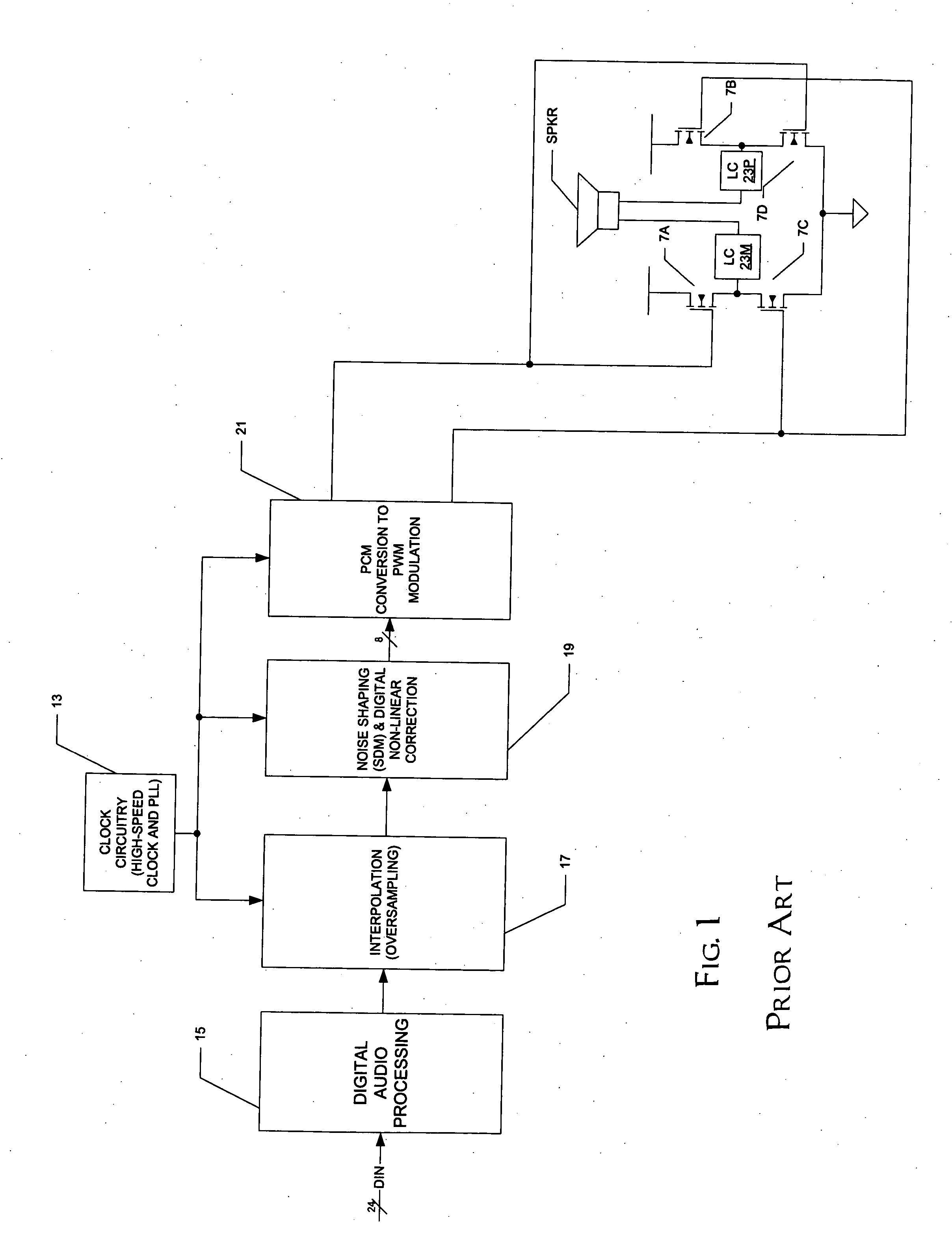
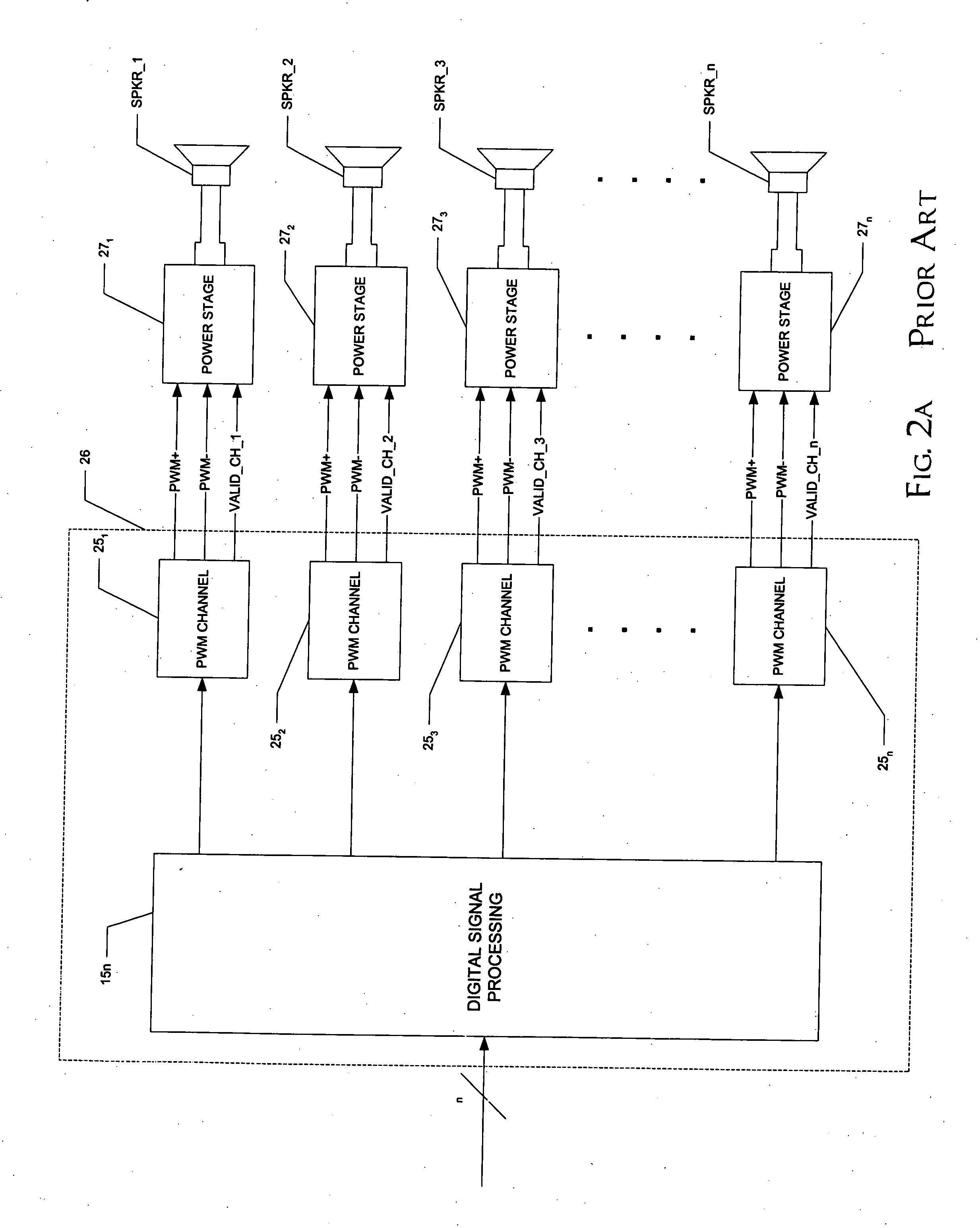
The technical problem addressed in this patent is how to implement advanced features such as inter-channel delay and reduction of click and popping sounds while minimizing the use of integrated circuits and avoiding constraints related to the design of printed circuit board layout and component placement.

Method used


Image

  • On-the-fly introduction of inter-channel delay in a pulse-width-modulation amplifier
  • On-the-fly introduction of inter-channel delay in a pulse-width-modulation amplifier
  • On-the-fly introduction of inter-channel delay in a pulse-width-modulation amplifier

Examples


Embodiment Construction

[0050] The present invention will be described in connection with its preferred embodiment, namely as implemented into a multiple-channel audio system, such as a home theater sound system, as it is contemplated that this invention is especially beneficial in such an application. However, it is also contemplated that this invention will be beneficial in many other applications in which class D amplifiers, or pulse-width-modulators, are applicable. Accordingly, it is to be understood that the following description is provided by way of example only, and is not intended to limit the true scope of this invention as claimed.

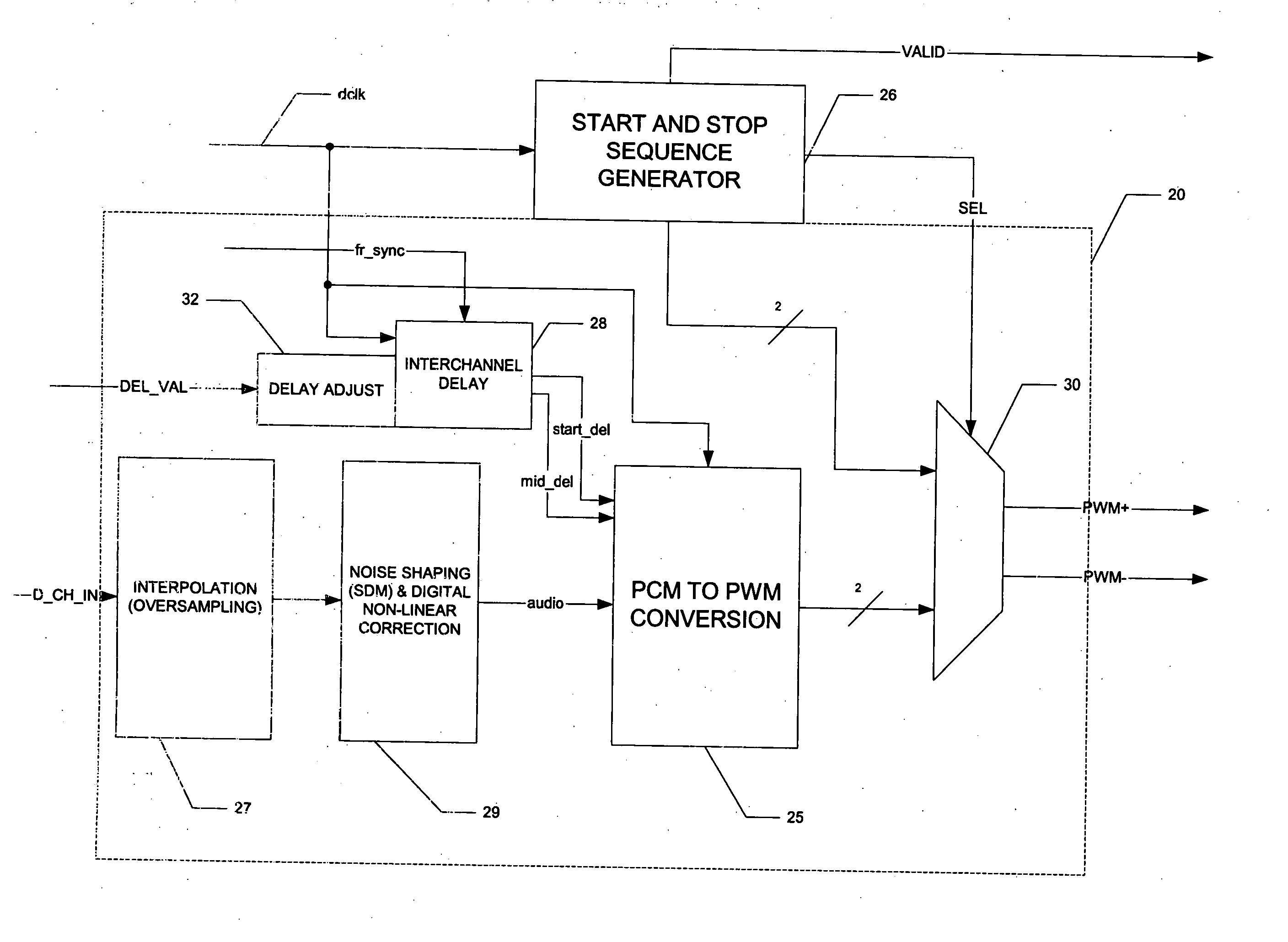
[0051]FIG. 3 illustrates the construction of a digital audio amplifier system constructed according to the preferred embodiment of the invention. In this example, this system is capable of driving four output audio channels from four separate digital inputs. It is, of course, contemplated that the system may drive more or fewer channels, depending upon the system req...


PUM


Abstract

A multiple-channel audio processor (10) and an associated plurality of power stages (22) in an audio system are disclosed. The audio processor (10) includes a plurality of audio amplifier channels (22), each of which includes a pulse-code-modulation (PCM) to pulse-width-modulation (PWM) conversion function (25), which generates PWM signals for application to the plurality of power stages (22). The audio amplifier channels (20) each also include an interchannel delay function (28) for delaying the PWM edges relative to other channels (20), for reducing noise. The audio amplifier channels (20) each also include delay adjust circuitry (32) for gradually increasing and decreasing the interchannel delay of the channel (20) on startup and shutdown. This permits a single control terminal (VALID) at the processor to globally enable and disable all of the power stages (22).

Description


Claims


Application Information

Patent Timeline
Owner TEXAS INSTR INC
Why Eureka
Try Eureka