Silent chain

a technology of chain and inner link, applied in the direction of chain elements, metal chains, driving chains, etc., can solve the problems of unbalanced load applied to the respective plate, unbalanced tensile load on the link plate, etc., to reduce the stress applied to the inner link plate positioned on the outermost side of improve the joint link row, and suppress the flexure of the guide plate and the connecting pin

Active Publication Date: 2006-05-18
TSUBAKIMOTO CHAIN CO
View PDF8 Cites 14 Cited by
  • Summary
  • Abstract
  • Description
  • Claims
  • Application Information

AI Technical Summary

Benefits of technology

[0014] Stress applied to the inner link plate positioned on an outermost side of a joint link row is decreased, and, at the same time, flexure of the guide plate and the connecting pin is suppressed. As a result, stresses are more uniformly distributed to the centrally located inner link plates of the guide link row, so that the balance of stresses exerted on all the inner link plates of the guide link row and the joint link row is improved.
[0015] Furthermore, because flexure of the guide plate and the connecting pin is suppressed, limited area contact between the connecting pins and the pin holes of the outermost link plates of the joint link rows is suppressed, reducing wear at that location. As a result, wear elongation of the chain is reduced, and the problems of noise and tooth jumping due to wear elongation of the chain can be prevented.
[0016] Furthermore, because the inner link plates are stacked in groups, the total area of sliding contact between the faces of the plates is significantly reduces, and friction losses are consequently also reduced.

Problems solved by technology

However, since the number of plates (26, 24a, 24b, 24a, 26) in the guide link row GL is different from the number of plates (25a, 25b, 25b, 25a) in the joint link row JL, the loads applied to the respective plates become unbalanced.
As a result, stress is not applied to all the inner link plates uniformly.
The bending of the connecting pins thus results in unbalanced tensile loads on the link plates, and the stress balance is made even worse because the guide link rows and the joint rows have different numbers of plates.
Consequently both the inner surfaces of the pin holes and the outer surfaces of the connecting pins tend to wear rapidly, causing chain elongation.

Method used


Image

  • Silent chain
  • Silent chain
  • Silent chain

Examples


Embodiment Construction

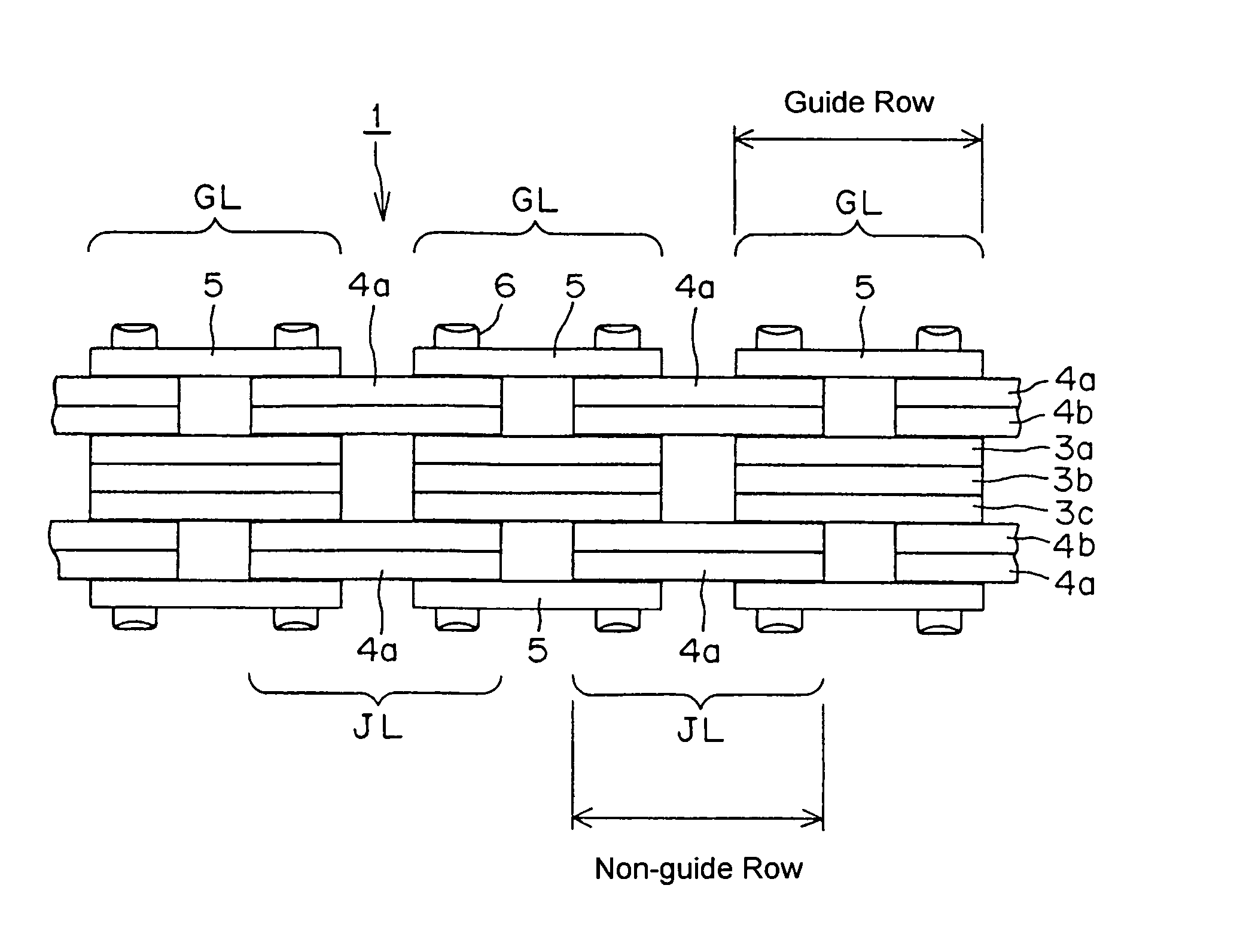
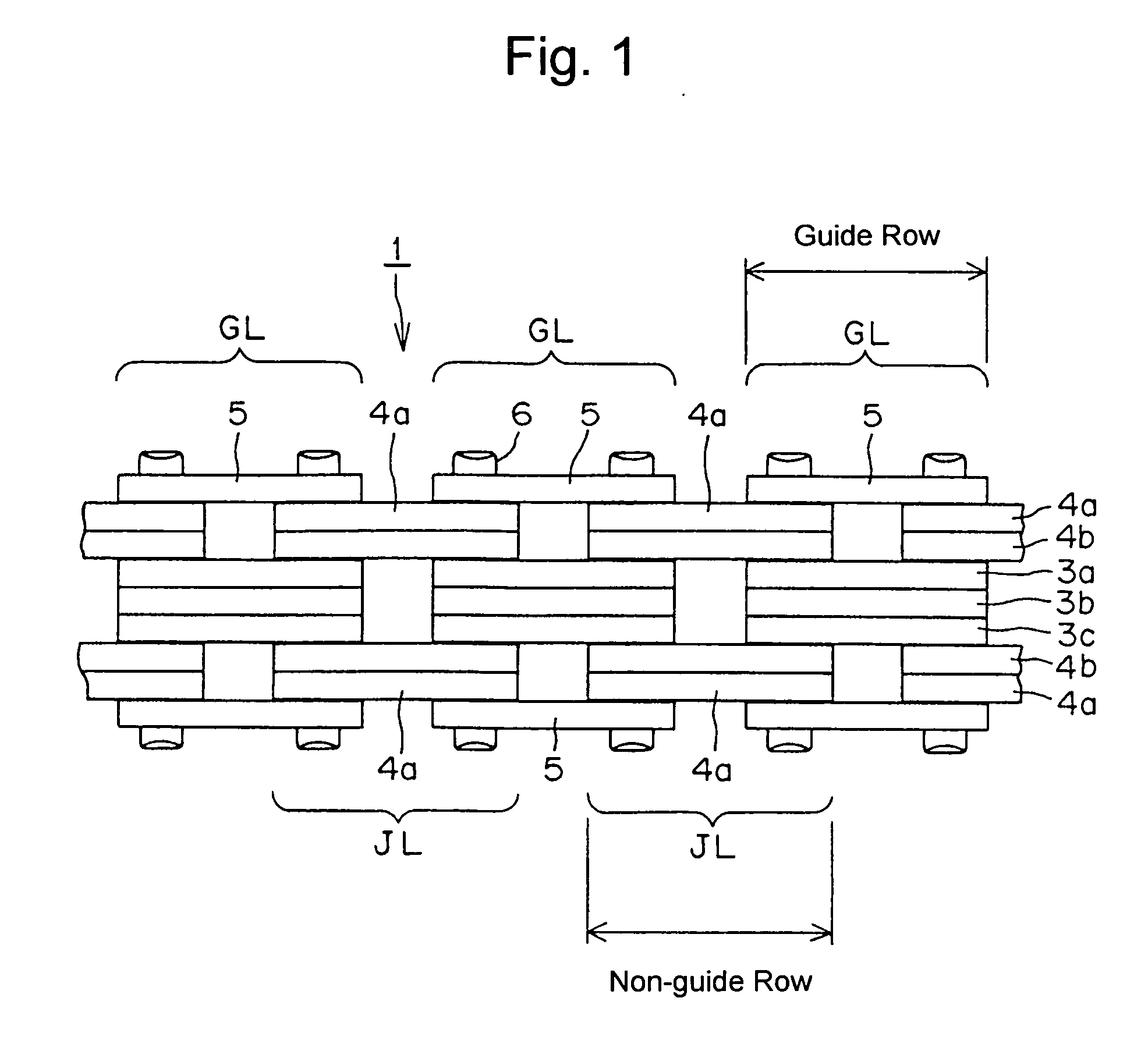
[0024] In the silent chain 1, shown in FIG. 1 inner link plates 3a, 3b and 3c, and a pair of guide plates 5, form guide link rows GL, and two sets of link plates 4a and 4b form each joint link row (or “non-guide” row) JL. The plates are connected by connecting pins 6.

[0025] Each of the inner link plates 3a, 3b, 3c, 4a, 4b has a pair of teeth (not shown), and a pair of pin holes (not shown), as in a conventional link plate. The thicknesses of all of the inner link plates 3a, 3b, 3c, 4a, 4b are preferably the same.

[0026] In each guide link row GL, the three inner link plates 3a, 3b and 3c are stacked together, with plate 3b being located at the center of the chain in the widthwise direction. Guide plates 5, which have no teeth, are arranged on both outermost sides of each guide link row GL.

[0027] In each joint link row JL a pair of inner link plates 4a and 4b, which are stacked against each other, is disposed between a plate 3a and a guide plate 5 of an adjacent guide link row, and...


PUM

PropertyMeasurementUnit
wear elongationaaaaaaaaaa
tensileaaaaaaaaaa
stressaaaaaaaaaa

Abstract

In an endless silent chain composed of alternating guide link rows and joint link rows connected by connecting pins, each guide link row is composed of a stack of three, centrally located, link plates and two outer guide plates, and each joint link row is composed of two pairs of link plates in abutting, side-by-side relationship. The pairs of link plates of the joint link rows extend into the spaces between the guide plates and the centrally located stack of each of two adjacent guide link rows.

Description

FIELD OF THE INVENTION [0001] This invention relates to silent chains used to transmit rotation from a driving sprocket to one or more driven sprockets, and more specifically to the suppression of wear elongation in silent chains. BACKGROUND OF THE INVENTION [0002] In a typical silent chain, a number of inner link plates, each having a pair of teeth and a pair of pin holes, are arranged in interleaved relationship in alternate “guide” link rows and non-guide link or “joint” link rows, extending widthwise of the chain. The guide link rows have guide plates at both ends, so that guide plates are provided along both sides of the chain. The alternate guide link rows and joint rows are connected articulably by connecting pins to form an endless loop. Typical silent chains of the type referred to above are shown and described in United States Patent Application Publication 2003 / 0195074 and U.S. Pat. No. 6,733,410. [0003] FIGS. 2(A) and 2(B) show an example of a conventional silent chain 2...

Claims


Application Information

Patent Timeline
Patent Type & Authority Applications(United States)
IPC IPC(8): F16G13/04
CPCF16G13/04B21L9/065F16G13/02
Inventor TOHARA, TAKASHIHIRAI, AKIRA
Owner TSUBAKIMOTO CHAIN CO
Why Eureka
Try Eureka