System and program for detecting disk array device bottlenecks

Inactive Publication Date: 2006-05-18
FUJITSU LTD
View PDF8 Cites 42 Cited by
  • Summary
  • Abstract
  • Description
  • Claims
  • Application Information

AI Technical Summary

Benefits of technology

[0014] Thus, an object of the present invention is to provide a system and a program, which are capable of appropriately detecting the occurrence of bottlenecks.

Problems solved by technology

In this manner, with conventional methods of detecting and identifying bottlenecks only on the basis of resource utilization ratio, there have been the problems that sometimes a bottleneck which ought to be eliminated is overlooked, and that sometimes a bottleneck elimination procedure is performed for a bottleneck which is not actually occurring.

Method used


Image

  • System and program for detecting disk array device bottlenecks
  • System and program for detecting disk array device bottlenecks
  • System and program for detecting disk array device bottlenecks

Examples


Embodiment Construction

[0040] In the following, embodiments of the present invention will be explained with reference to the figures. However, the technical range of the present invention is not limited to these embodiments.

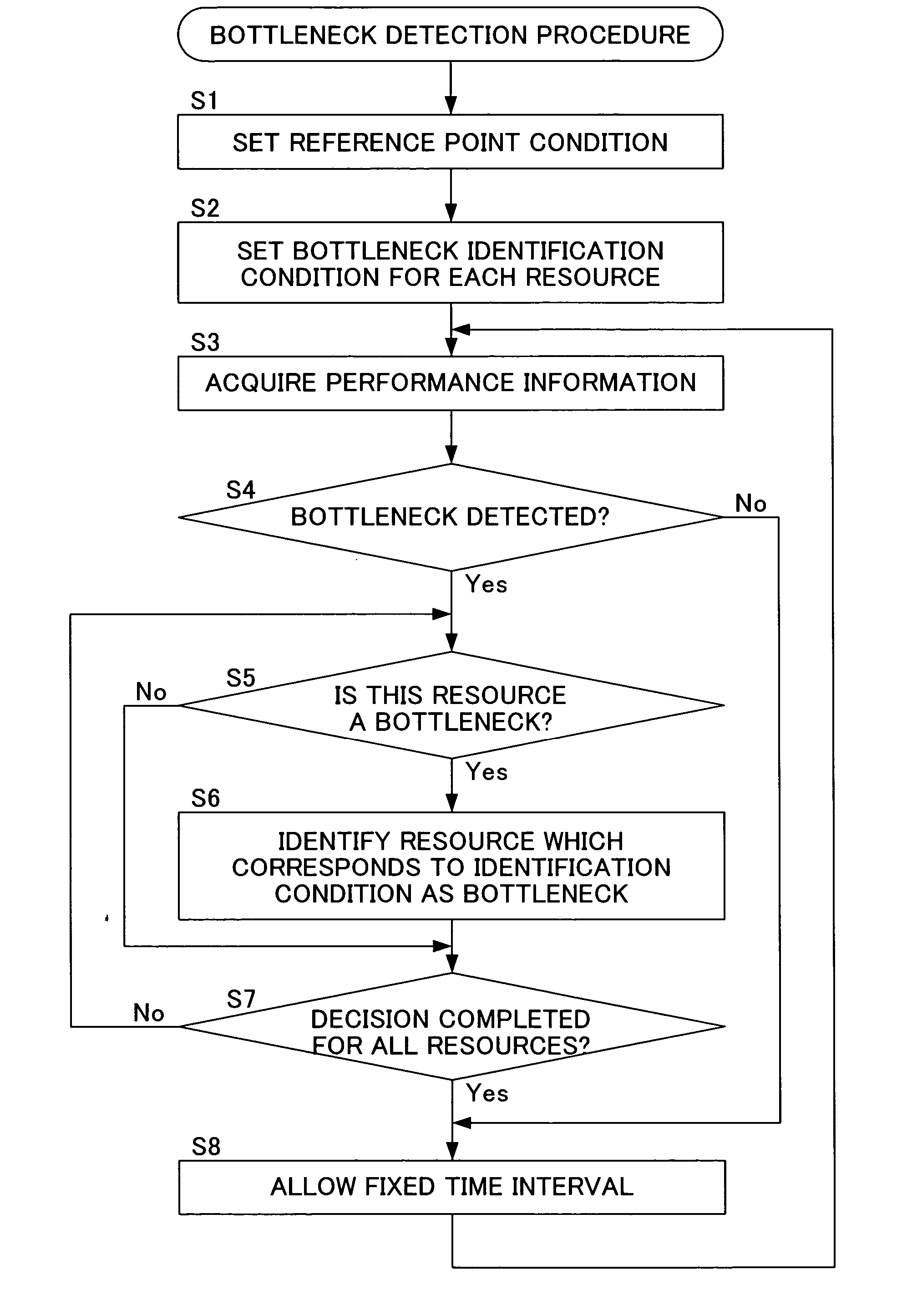
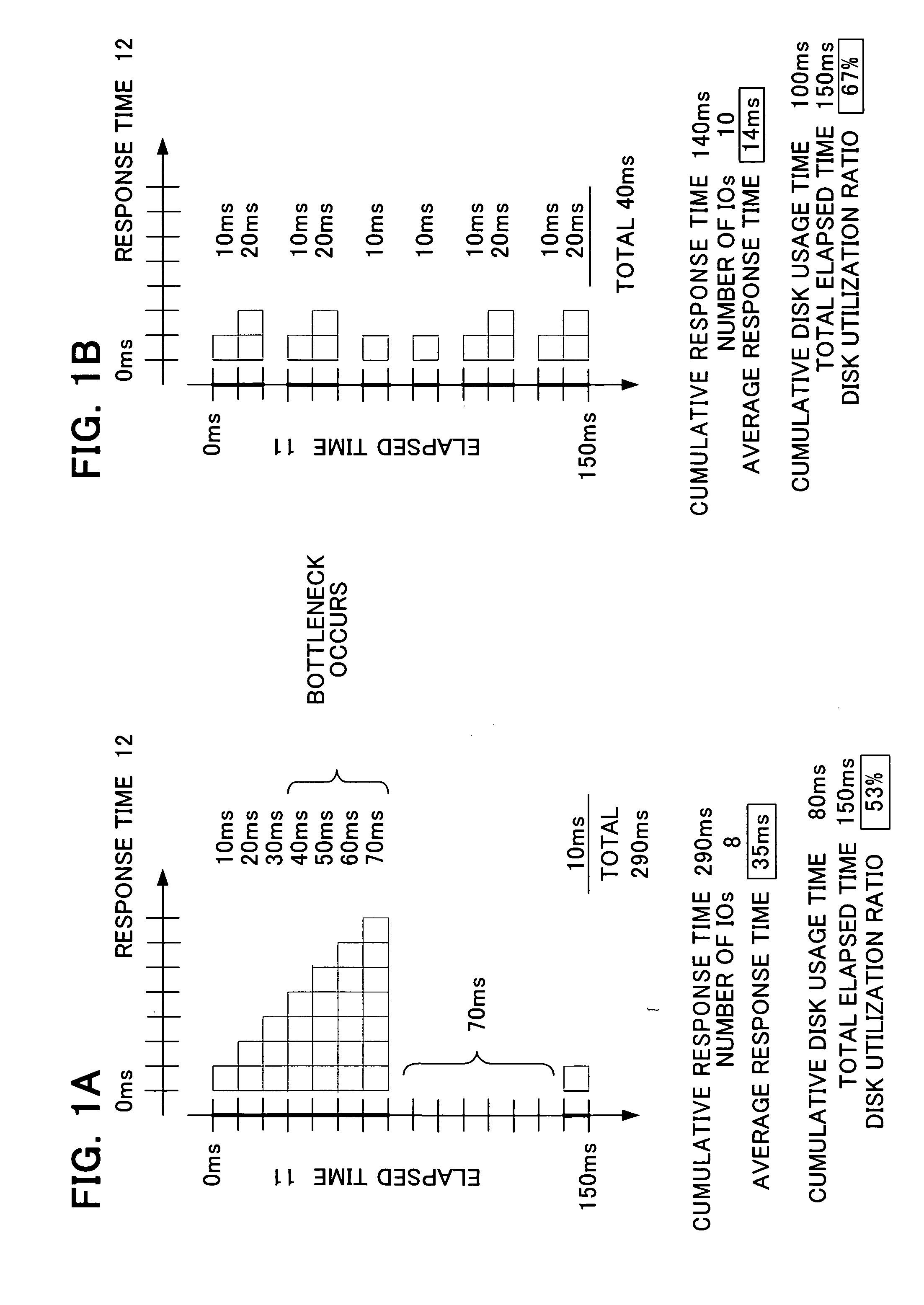
[0041] As shown in FIG. 1, when a bottleneck occurs, the response time which is required for the processing of IO requests increases. Accordingly, in order to detect the occurrence of bottlenecks, it should be sufficient to monitor the response time. Thus, in the embodiments of the present invention, it is not the case that the resource utilization ratio is monitored, and bottlenecks are detected from the resource utilization ratio, as in the prior art; rather, a reference point for the detection of bottlenecks is determined based upon a condition which is set in relation to the response time. And the history of the performance information before the reference point is referred to, and bottlenecks are identified based upon an identification condition which is set in relation to the re...


PUM


Abstract

A system is provided in which a server which provides a service to a client terminal, a disk array device upon which data used by the server is stored, and a monitor terminal which detects a bottleneck on the disk array device, are connected via a network. The disk array device or the server calculates performance information including the number of IO requests issued by the server, the times required for processing the IO requests, and a resource utilization ratio for each resource included in the disk array device. The monitor terminal establishes a reference point based upon an average response time obtained by dividing the processing time included in the performance information by the number of the IO requests. And the system is characterized in that a resource is identified as a bottleneck, based upon the resource utilization ratio in a predetermined interval before the reference point.

Description

CROSS REFERENCE TO RELATED APPLICATIONS [0001] This application is a continuation of International Application No. PCT / JP03 / 10425, filed on Aug. 19, 2003, and International Application No. PCT / JP2004 / 011780, filed on Aug. 17, 2004, now pending, herein incorporated by reference.TECHNICAL FIELD [0002] The present invention relates to a system which includes a disk array device and a server which performs input and output of data to and from this disk array device. BACKGROUND ART [0003] A system in which a server which provides services to client terminals via a network, and a disk array device which stores various types of data used by application programs operating upon this server, are connected together, is widely used as a current business system. When, with this type of system, the time period accompanying the processing of an application becomes great, the service which is provided to the client terminals deteriorates undesirably. Accordingly, various types of information (perfo...

Claims


Application Information

Patent Timeline
Patent Type & Authority Applications(United States)
IPC IPC(8): G06F15/173G06F3/06G06F11/34G06F12/00G06F13/10
CPCG06F11/3419G06F11/3452G06F2201/81
Inventor KATO, TADAOMIHIYOSHI, KEIKOSAKAI, JUICHIHIRABAYASHI, NAOKIYAMATO, TAKAAKIHORIKOSHI, TOMONARI
Owner FUJITSU LTD
Why Eureka
Try Eureka