

Fluid expansion-distribution assembly
- Summary
- Abstract
- Description
- Claims
- Application Information
AI Technical Summary
Benefits of technology
Problems solved by technology
Method used
Image

Examples
Embodiment Construction
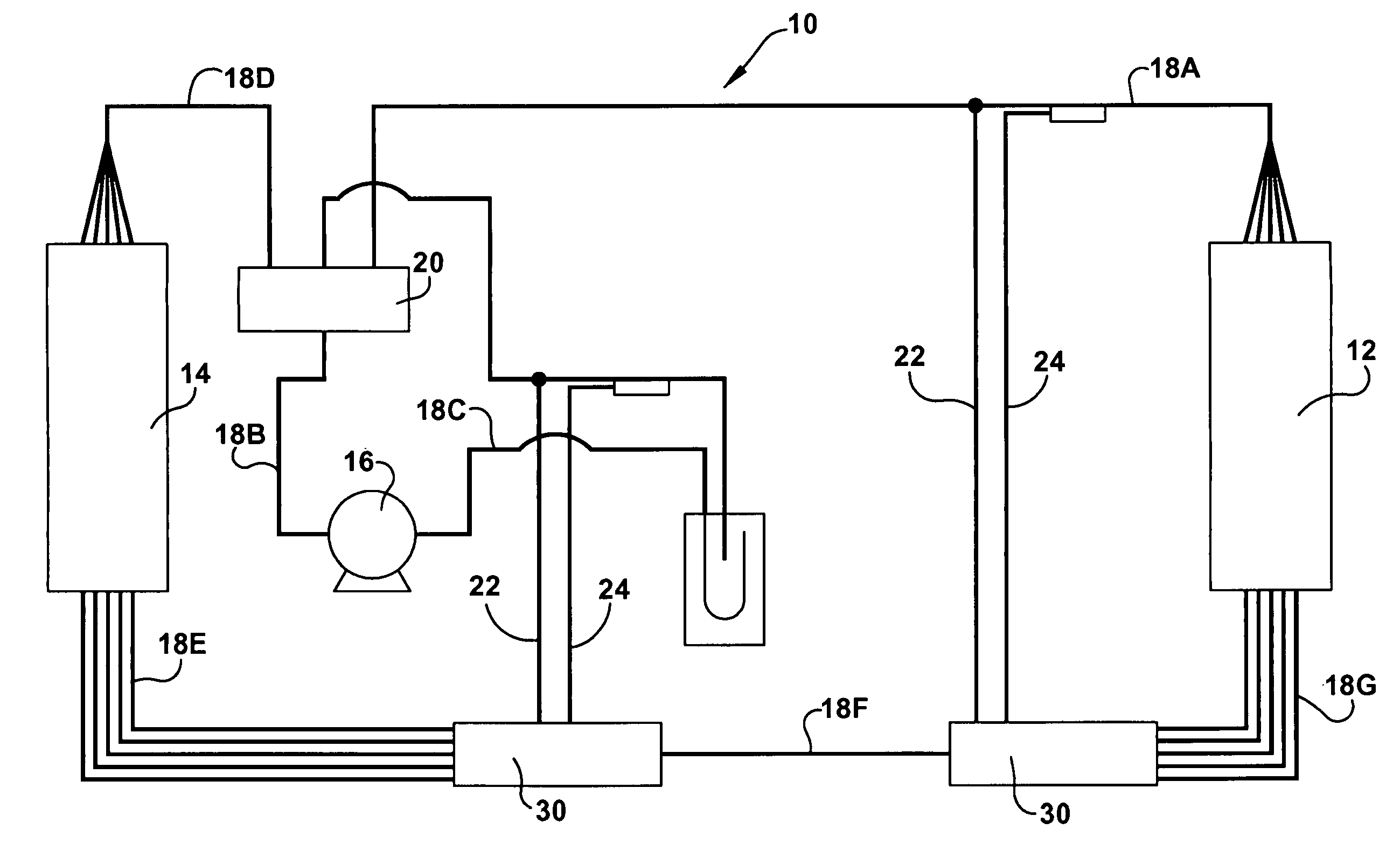
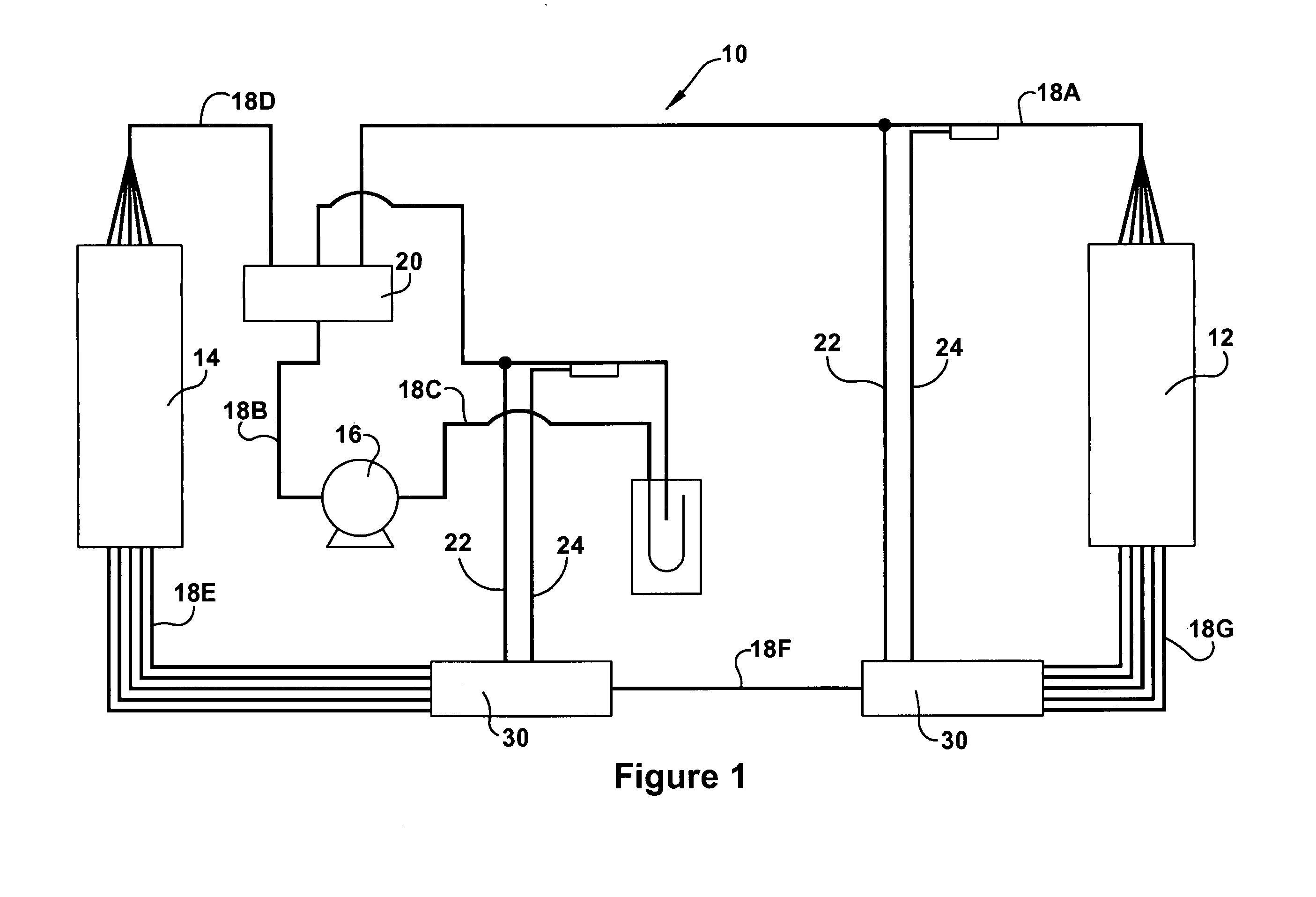
[0018] Referring now to the drawings, and initially to FIG. 1, a heatpump system 10 according to the present invention is schematically shown. The heatpump system 10 can be used to control the temperature of a certain medium (e.g., air inside a building) and generally comprises an evaporator 12, a condenser 14, and a compressor 16. A plurality of lines 18 (e.g., pipes, tubes, ducts) connect these components so that refrigerant fluid can cycle therethrough. The evaporator 12 can be located within the medium (i.e., it can be located inside the building) and the compressor can be located remote from the medium (i.e., it can be located outside of the building).
[0019] The heatpump system 10 can operate in a first (forward) direction, whereat it cools the medium, and a second (reverse) direction, whereat it heats the medium. A reversing valve 20, or other flow-direction-determining means, can be used to select the direction of flow through the heatpump system 10. In the first (i.e., forw...
PUM
 Abstract
Description
Claims
Application Information