Apparatus and method for specific interstitial or subcutaneous diffusion and dispersion of medication

Active Publication Date: 2007-06-19
BAXTER INT INC +1
View PDF19 Cites 12 Cited by
  • Summary
  • Abstract
  • Description
  • Claims
  • Application Information

AI Technical Summary

Benefits of technology

[0015]In a preferred embodiment, the fluid flow path through the lumen is of substantially uniform inside diameter between the proximal end and the distal end. However, flow paths having nonuniform inside diameters are also within contemplation. Embodiments having the latter configuration may be structured to minimize a pressure drop in the lumen across a dispersion zone.

Problems solved by technology

As the migrating medication is dispersed, inefficiencies in treatment may result.
In some instances, excessive doses have been utilized to compensate for this dispersion effect, inherently resulting in exposure of the treatment site to unnecessary levels of medication.
Such exposure not only wastes medication that may be expensive, but may also have a detrimental impact on the surrounding tissue as well as precipitating adverse side effects in other aspects of the patient's systemic physiology.
Another challenge imposed by the foregoing dispersion conundrum involves the rate and frequency of introduction of medication to surgical and general treatment sites.
The logistical difficulties of scheduling and commuting have discouraged patients from maintaining an optimal treatment regime.
A technical difficulty exists with respect to the accuracy of the placement of the medicinal delivery orifice relative to the desired treatment site.
Use of flexible catheters allows for potential migration of the catheter to a range of subdural or intra-cavity positions that may be undesirable, increasing the desirability of a more rigid delivery structure with means for monitoring depth of insertion.
A specific problem associated with infusion drug delivery through plural port catheters (e.g., “soaker catheters”) is the inherent differences in the “flow through” characteristics of each of a plurality of discharge orifices.

Method used


Image

  • Apparatus and method for specific interstitial or subcutaneous diffusion and dispersion of medication
  • Apparatus and method for specific interstitial or subcutaneous diffusion and dispersion of medication
  • Apparatus and method for specific interstitial or subcutaneous diffusion and dispersion of medication

Examples


Embodiment Construction

[0029]Embodiments of the present invention will be hereinafter described with reference to the accompanying drawings. It would be understood that these illustrations are not to be taken as actual views of any specific apparatus or method of the present invention, but are merely exemplary, idealized representations employed to more clearly and fully depict the present invention than might otherwise be possible. Additionally, elements and features common between the drawing figures retain the same numerical designation.

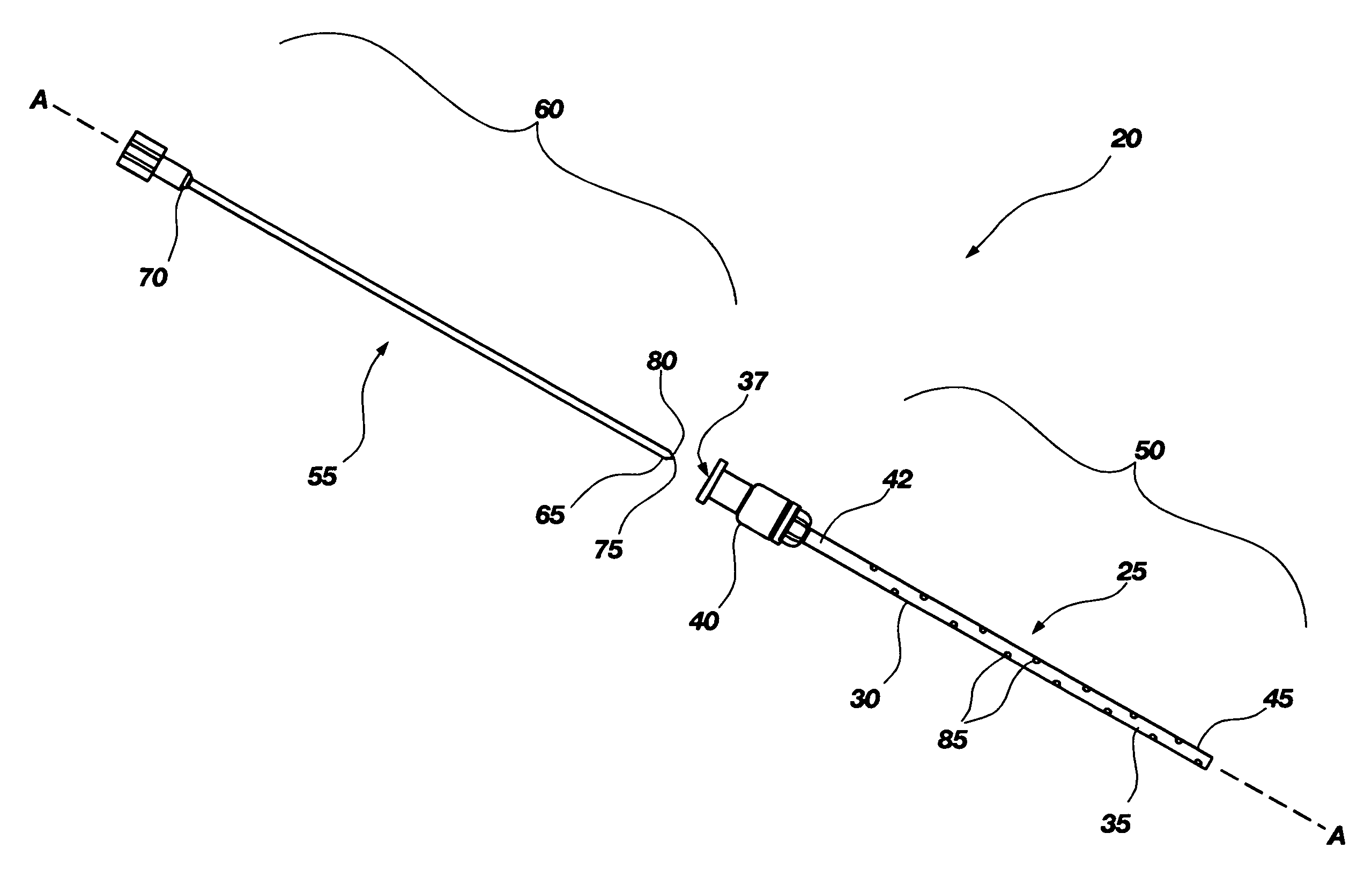
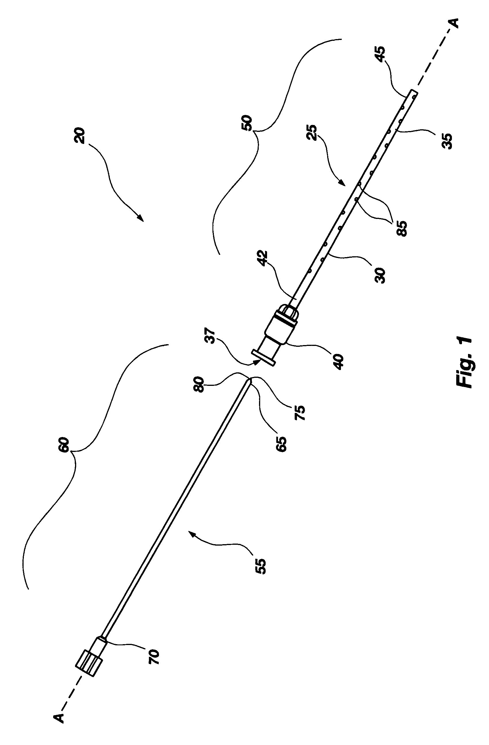
[0030]Referring to FIG. 1, an exploded side view of a preferred embodiment of a medical infusion tubular element assembly, designated generally as 20, is illustrated. The tubular element assembly 20 comprises a tubular element 25 and a stylet 55. Tubular element 25 includes a wall 30 which defines an elongate lumen 35, wherein the elongate lumen 35 includes a fluid flow path 37 extending through the tubular element 25 along axis A-A. The tubular element 25 may include a...


PUM


Abstract

A medication discharge assembly useful in patient systems includes a tubular element and a stylet. In a first, closed position, the stylet is seated within the tubular element and may provide a piercing point facilitating insertion of the tubular element to a treatment site. In a second, open position, the stylet is removed from the tubular element, and the tubular element provides a travel pathway for a drug introduced to the tubular element at a proximal connection port for specific interstitial and subcutaneous diffusion and dispersion of medication along the tubular element's length near a distal discharge port through disparate perforations, which may be formed as striations of increasing length nearer the distal discharge port. The stylet in the first position may be oriented to seal this travel pathway. Depth-finding features associated with the tubular element, visually perceptible and particularly useful for placement of the assembly, may be included.

Description

CROSS-REFERENCE TO RELATED APPLICATIONS[0001]Under the provisions of 35 U.S.C. § 119(e), priority is claimed from U.S. Provisional Patent Application Ser. No. 60 / 272,867 filed on Mar. 2, 2001.TECHNICAL FIELD[0002]This invention relates generally to medication infusion systems and is specifically directed to such systems for specific interstitial diffusion and dispersion of medication. It provides a particularly useful application for uniform dispersion of medication to perfuse a treatment site including a patient pain interface.BACKGROUND[0003]Heretofore, introduction of medication at a preferred site within the body of a patient has been accomplished through delivery structure in either of essentially two forms, namely, injection through a needle or infusion through a catheter. Each of these methodologies has resulted in delivery of medication primarily to a location immediately adjacent to the distal tip of the needle or catheter. After injection through a needle or infusion throu...

Claims


Application Information

Patent Timeline
IPC IPC(8): A61M5/178A61M25/00A61M25/06A61M31/00
CPCA61M25/06A61M31/00A61M2025/0057
Inventor SORENSON, JAMES LEVOYHAIGHT, LEVOY GOLDEN
Owner BAXTER INT INC
Why Eureka
Try Eureka