Magnetic flow meter providing quasi-annular flow

Inactive Publication Date: 2009-12-08
ONICON INC
View PDF4 Cites 29 Cited by
  • Summary
  • Abstract
  • Description
  • Claims
  • Application Information

AI Technical Summary

Benefits of technology

[0013]It should be noted that the tube may be fitted on one end, or preferably on both ends, with flow obstructing attachments so that the proportion of the total fluid flow entering the meter which passes through the tube can be selected for a particular application. For example, a meter intended for very high flow rates could essentially have an unobstructed

Problems solved by technology

These meters are characterized by an unobstructed flow passage offering very low pressure drop and high tolerance to solids in the fluid, high measurement precision, hi

Method used


Image

  • Magnetic flow meter providing quasi-annular flow
  • Magnetic flow meter providing quasi-annular flow
  • Magnetic flow meter providing quasi-annular flow

Examples


Embodiment Construction

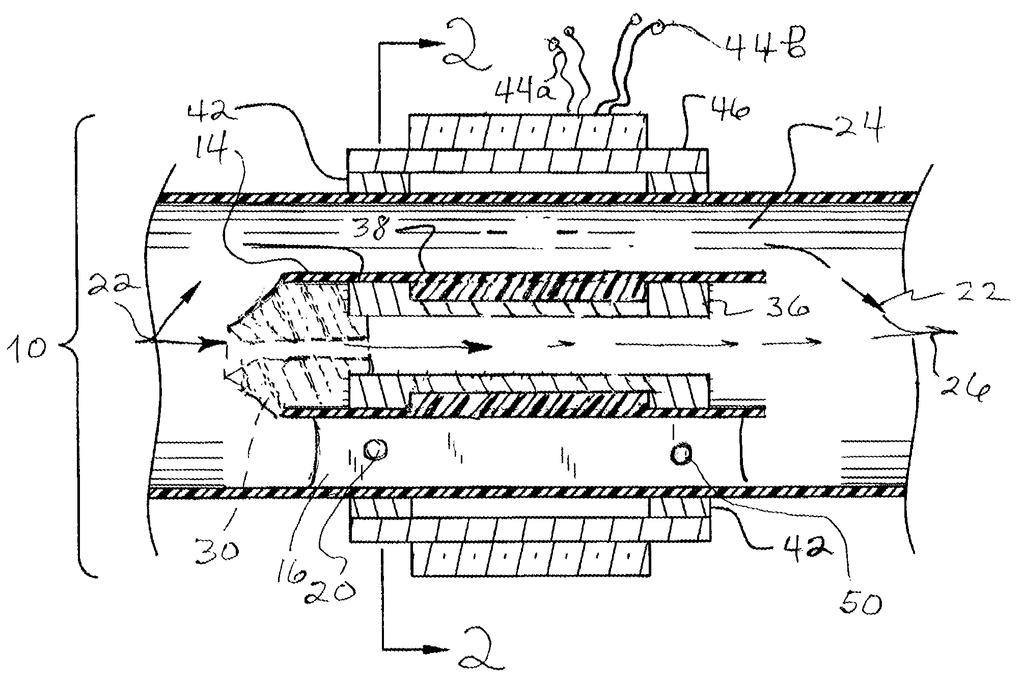
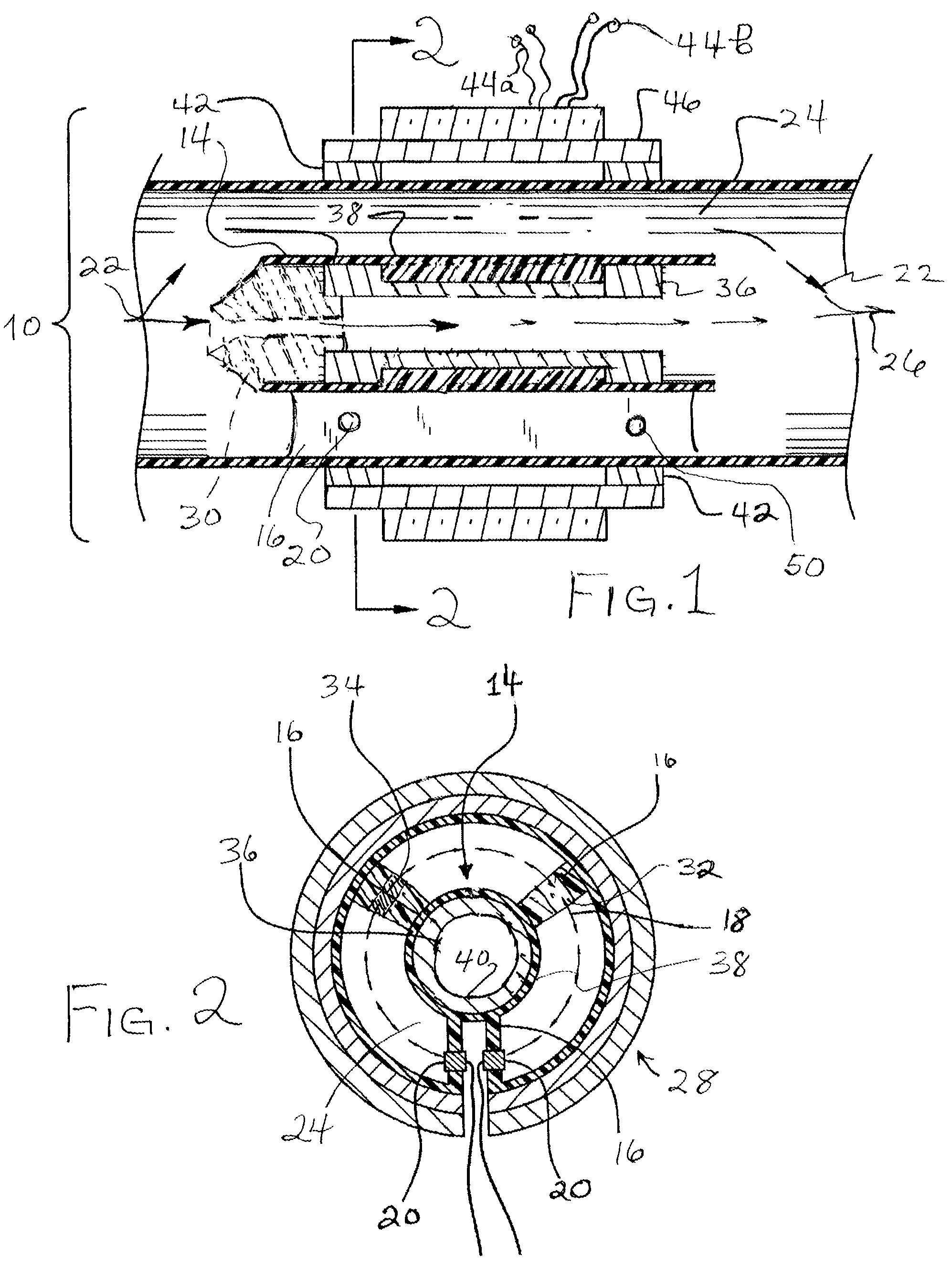
[0018]In studying this Detailed Description, the reader may be aided by noting the definitions of certain words and phrases used throughout this patent document. Wherever those definitions are provided, those of ordinary skill in the art should understand that in many, if not most instances, such definitions apply to both preceding and following uses of such defined words and phrases. In particular, the terms “pipe” and “meter body” and “tubular meter body” are used to describe an external portion of the meter of the invention and are distinguished from an inner, generally axially disposed portion of the meter that is generally referred to as the “inner tube”, “axial body” or “central body”.

[0019]Turning now to FIG. 1 of the drawing, one finds a sensing portion 10 of a magnetic flow meter 12 of the invention designed to extend a product line based upon the teachings of U.S. Pat. No. 6,571,642 to situations in which the flow impedance created by the presence of a central streamlined ...


PUM


Abstract

An in-line magnetic flow meter has an electrically insulated quasi-annular voltage sensing path defined between an internal wall of a meter body and an outer wall of an axially disposed hollow tube. Although less than 100% of the fluid flow passes through the sensing region, the choice of an inner tube reduces flow impedance introduced by the meter, when compared to other meters providing a quasi-annular sensing path. In addition, by forming two electromagnet coils on a single core and using axially separated pairs of electrodes, the present arrangement allows one to provide two flow meters in the space normally occupied by one.

Description

BACKGROUND OF THE INVENTION[0001]1. Field of the Invention[0002]This invention relates to apparatus and method for determining the rate of flow of a fluid by a magnetic flow meter that measures an electrical potential difference developed in the fluid as the fluid moves through a magnetic field.[0003]2. Background Information[0004]In most prior art in-line magnetic flow meters, the electrical potential difference developed in the fluid is sensed by a pair of electrodes contacting the liquid and spaced apart from each other by the diameter of a round flow sensing passage. A magnetic field generated orthogonal to both the line between the electrodes and the direction of flow through the sensing passage is provided by two coils of wire located on opposite sides of and outside of the passage. Sophisticated electronics are used to energize the magnetic field, to amplify the tiny flow-related signals generated, and to reject various noise and drift signal components which would otherwise ...

Claims


Application Information

Patent Timeline
IPC IPC(8): G01F1/58
CPCG01F1/588
Inventor FELLER, MURRAY F
Owner ONICON INC
Why Eureka
Try Eureka