

Distribution tray, vessel, or method relating thereto
- Summary
- Abstract
- Description
- Claims
- Application Information
AI Technical Summary
Benefits of technology
Problems solved by technology
Method used
Image

Examples
Embodiment Construction
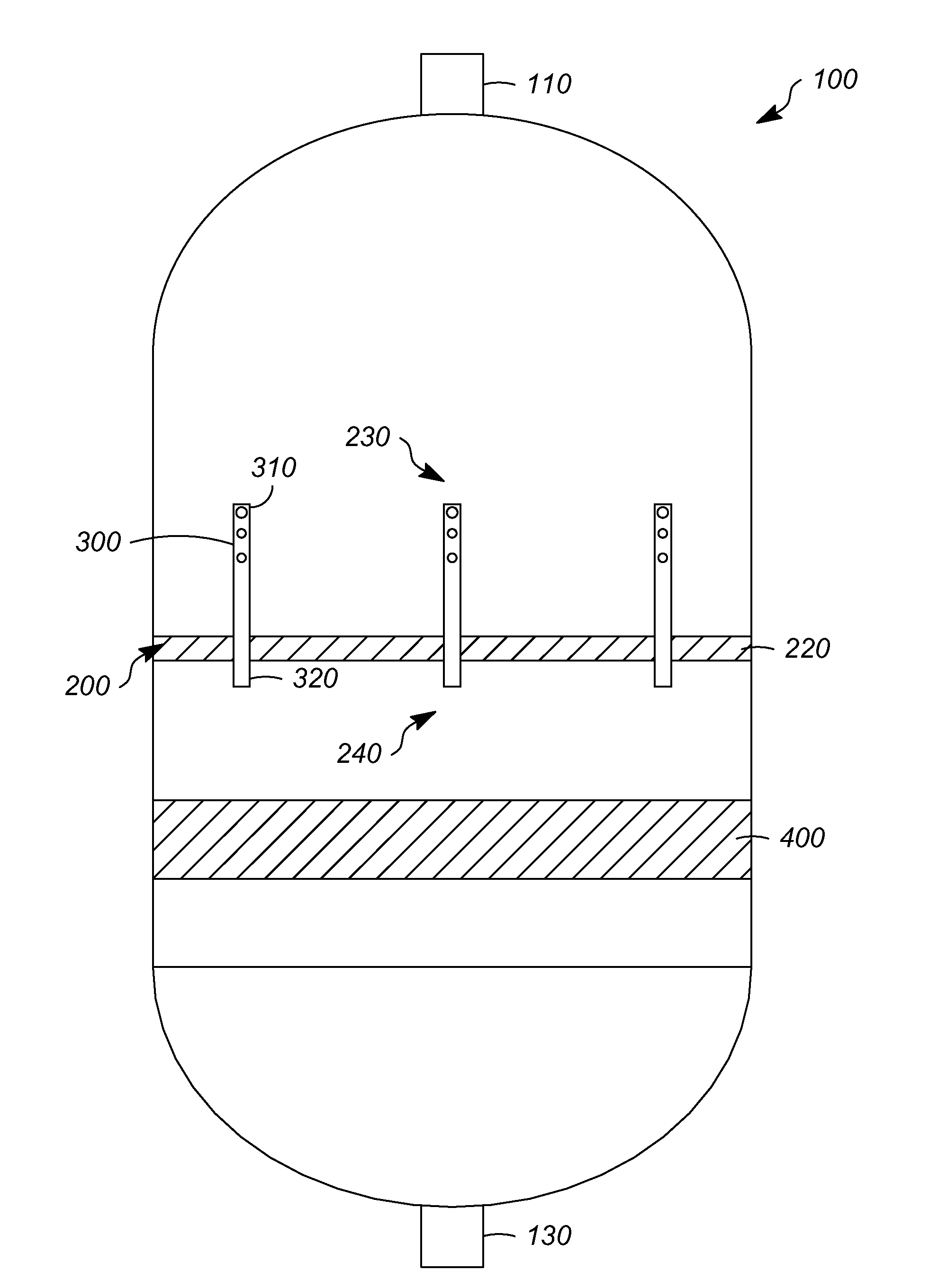
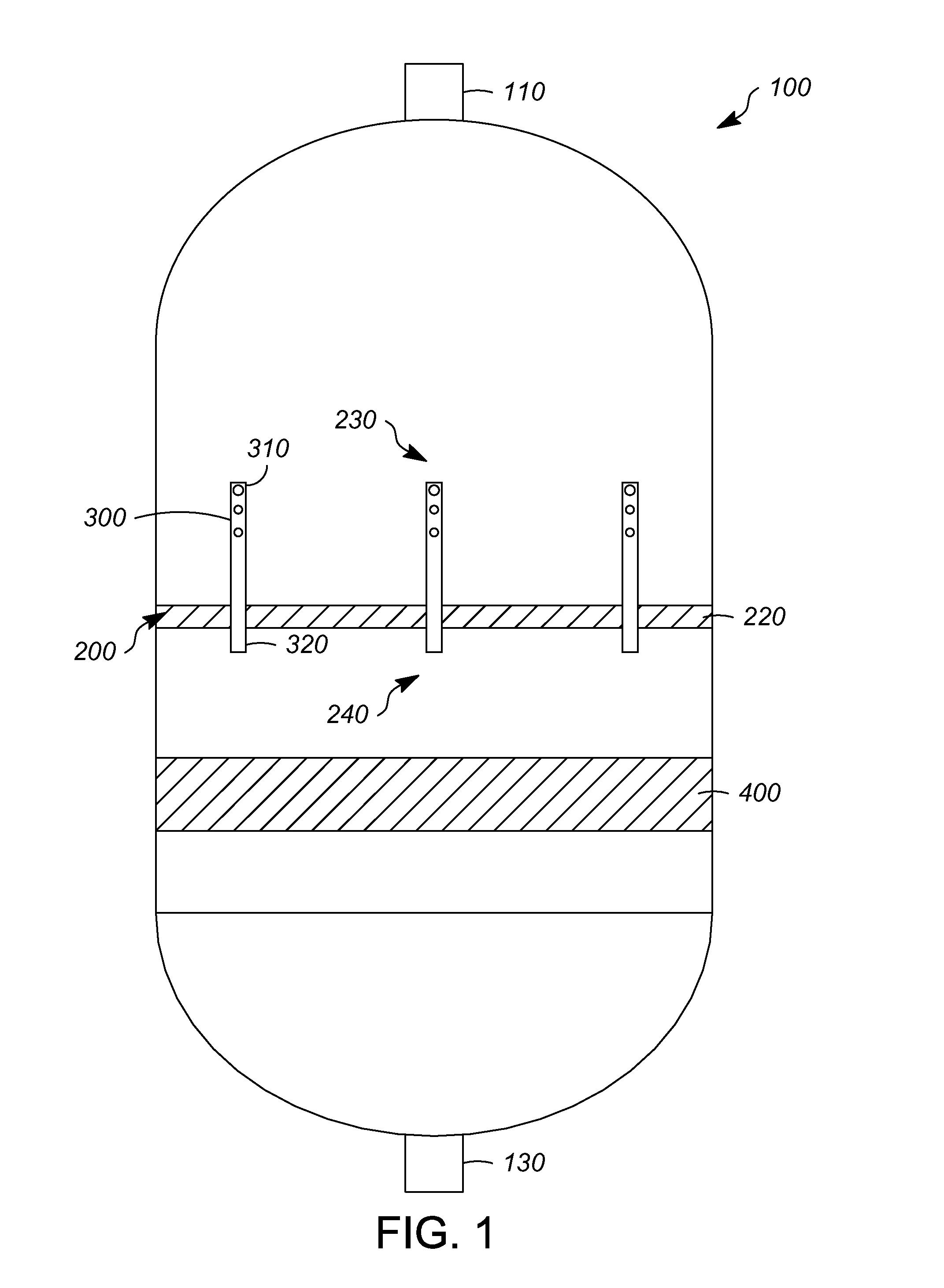
[0026]Referring to FIGS. 1-2, a vessel 100 is depicted having an inlet 110 and an outlet 130. The vessel 100 can receive a feed of a fluid, including a liquid or a mixed-phase fluid, such as one or more liquids and gases, through the inlet 110. Generally, the feed is distributed in the vessel containing a fixed bed of particles, such as a catalyst. Although a reactor is disclosed herein, it should be understood that other types of vessels such as an absorber or a mass transfer vessel can also use the embodiments disclosed herein, and other materials can be contained instead of or in addition to the catalyst, such as an absorbent. Furthermore, the vessel 100 can be manufactured from any suitable material, such as carbon or stainless steel.
[0027]The vessel 100 can include a distribution tray 200 and a packed bed 400 of particles, such as a catalyst. Although only one distribution tray 200 and one packed bed 400 are depicted in this exemplary embodiment, it should be understood that th...
PUM
| Property | Measurement | Unit |
|---|---|---|
| Diameter | aaaaa | aaaaa |
| Elevation | aaaaa | aaaaa |
| Distribution | aaaaa | aaaaa |
Abstract
Description
Claims
Application Information