Paintball marker featuring high effectiveness airflow

Inactive Publication Date: 2006-05-25
RICE JACK V
View PDF18 Cites 16 Cited by
  • Summary
  • Abstract
  • Description
  • Claims
  • Application Information

AI Technical Summary

Benefits of technology

[0025] Another object of the present invention is to provide a paintball marker which is easy to use and easy to aim for successful delivery of a paintball to a targ

Problems solved by technology

Such known prior art paintball markers have not been entirely satisfactory in some aspects.
One problem encountered with many paintball markers is that after some period of use the paintball marker will cease operating properly.
Because many of the elements of the paintball marker are hidden within an enclosed body it is often difficult to determine which portion of the paintball marker requires service to again achieve satisfactory performance.
For instance, if the trigger is toggled with a ball in the firing chamber and yet the ball has not fired and no charge of compressed air leaves the firearm, a multitude of different potential problems could produce such a result.
It is thus difficult for a user or maintenance personnel to diagnose the problem.
Another problem encountered with many prior art p

Method used


Image

  • Paintball marker featuring high effectiveness airflow
  • Paintball marker featuring high effectiveness airflow
  • Paintball marker featuring high effectiveness airflow

Examples


Example

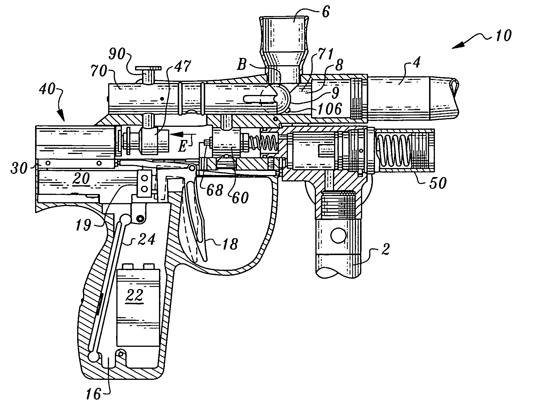
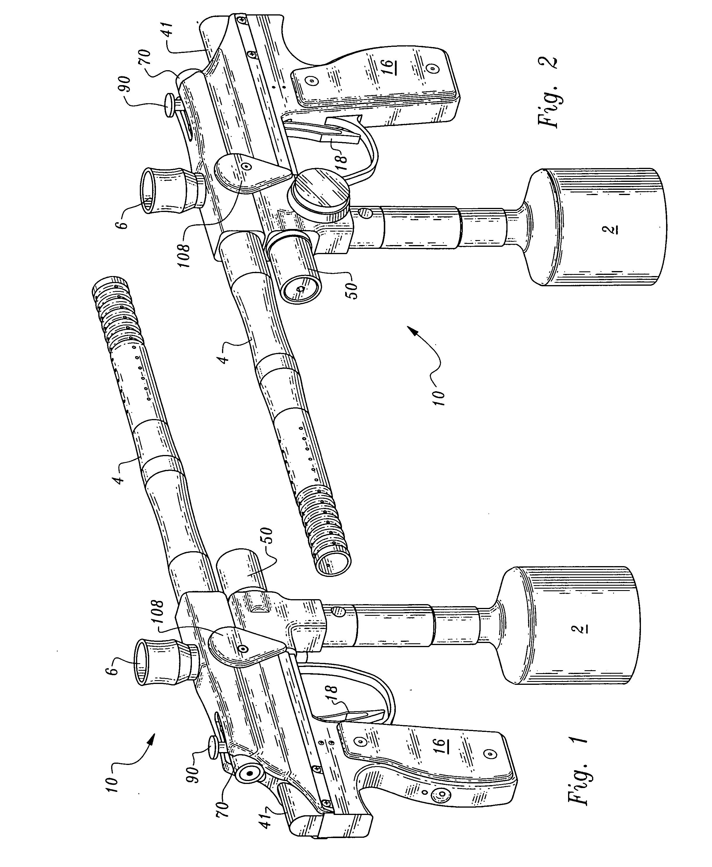
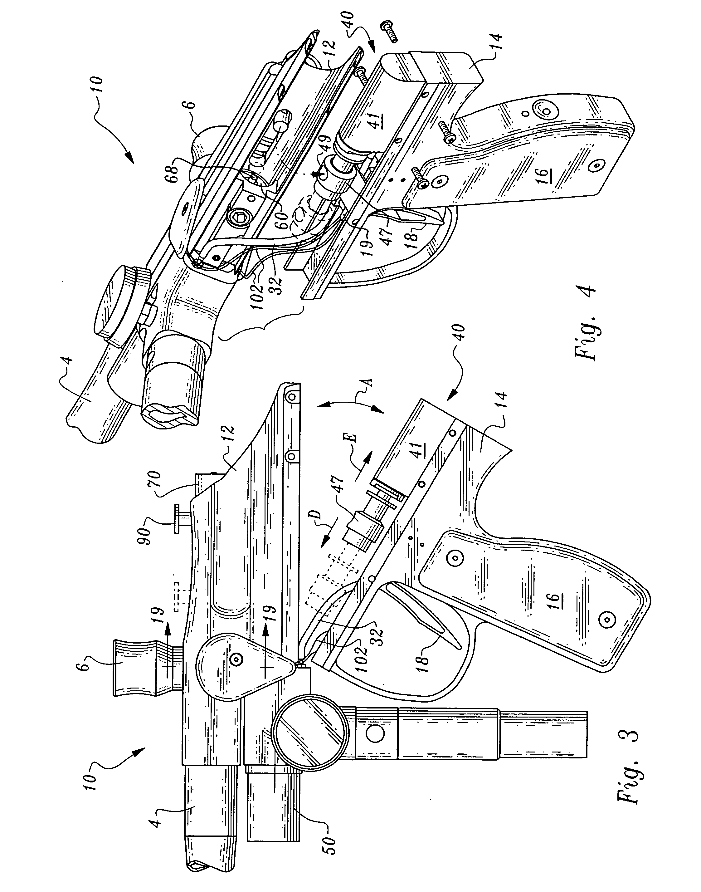
[0047] Referring to the drawings, wherein like reference numerals represent like parts throughout the various drawing figures, reference numeral 10 (FIGS. 1 and 2) is directed to a paintball marker according to a preferred embodiment of this invention. This paintball marker 10 is configured to cause air from an air supply 2 to be delivered to a firing chamber 8 (FIG. 7) for firing of a paintball B out of a barrel 4 and toward a target. Control of firing of the paintball marker 10 is provided by actuation of a trigger 18 which is operatively coupled to a main valve 60 (FIG. 7) to allow high pressure air to pass selectively from the air supply 2 up to the firing chamber 8 in response to actuation of the trigger 18.

[0048] In essence, and with particular reference to FIGS. 1-6, basic details of the paintball marker 10 are described. To cause the trigger 18 to open the main valve 60, preferably an electropneumatic valve 20 (FIGS. 5 and 6) is coupled to the trigger 18. The electropneumat...


PUM


Abstract

A paintball marker or other compressed gas firearm is provided including a ram driven by an electropneumatic valve when a trigger is actuated to cause a main valve between a high pressure air supply and a firing chamber to be opened. This ram assembly is independent from the main valve structurally and coupled to the air supply and electropneumatic valve sufficiently flexibly to allow the ram assembly to be operable when the ram assembly is displaced away from the main valve. A bolt is provided for directing pressurized air from the main valve to the firing chamber when the main valve is opened, and with the bolt configured to provide a high pressure air pathway which has a high degree of effectiveness in driving the ball out of the firing chamber without distorting a trajectory of the ball. The bolt can be stationary when air is flowing past the bolt.

Description

CROSS-REFERENCE TO RELATED APPLICATIONS [0001] This application claims benefit under Title 35, United States Code §119(e) of U.S. Provisional Application No. 60 / 541,556 filed on Feb. 3, 2004. This application also incorporates by reference the entire contents of U.S. Pat. No. 6,802,306 and U.S. patent application Ser. No. 10 / 877,742, having a filing date of Jul. 8, 2004. FIELD OF THE INVENTION [0002] The following invention relates to paintball markers and other firearms which deliver a projectile through force applied by compressed air or other gases. More particularly, this invention relates to paintball markers or related firearms which include a ram assembly between a trigger and a high pressure valve which can be inspected and tested while separated from other portions of the marker, and markers which control airflow for projectile launch with a high degree of effectiveness. BACKGROUND OF THE INVENTION [0003] Paintball markers are known in the art for firing projectiles in the ...

Claims


Application Information

Patent Timeline
IPC IPC(8): F41B11/00
CPCF41B11/71F41B11/723F41B11/722F41B11/724
Inventor RICE, JACK V.
Owner RICE JACK V
Why Eureka
Try Eureka