Building element including solar energy converter

Inactive Publication Date: 2006-05-25
GENERAL ELECTRIC CO
View PDF50 Cites 71 Cited by
  • Summary
  • Abstract
  • Description
  • Claims
  • Application Information

AI Technical Summary

Problems solved by technology

Solar energy converters, such as photovoltaic or thermal converters, typically have high material cost, high installation cost and thus a hig

Method used


Image

  • Building element including solar energy converter
  • Building element including solar energy converter
  • Building element including solar energy converter

Examples


Embodiment Construction

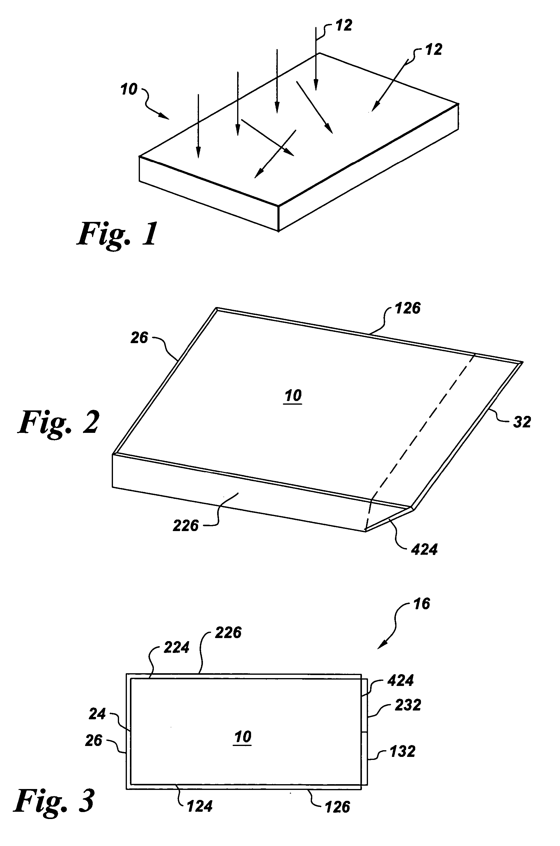
[0015]FIG. 1 is a perspective view of light 12 contacting a substrate 10 from various directions (diffuse and / or direct).

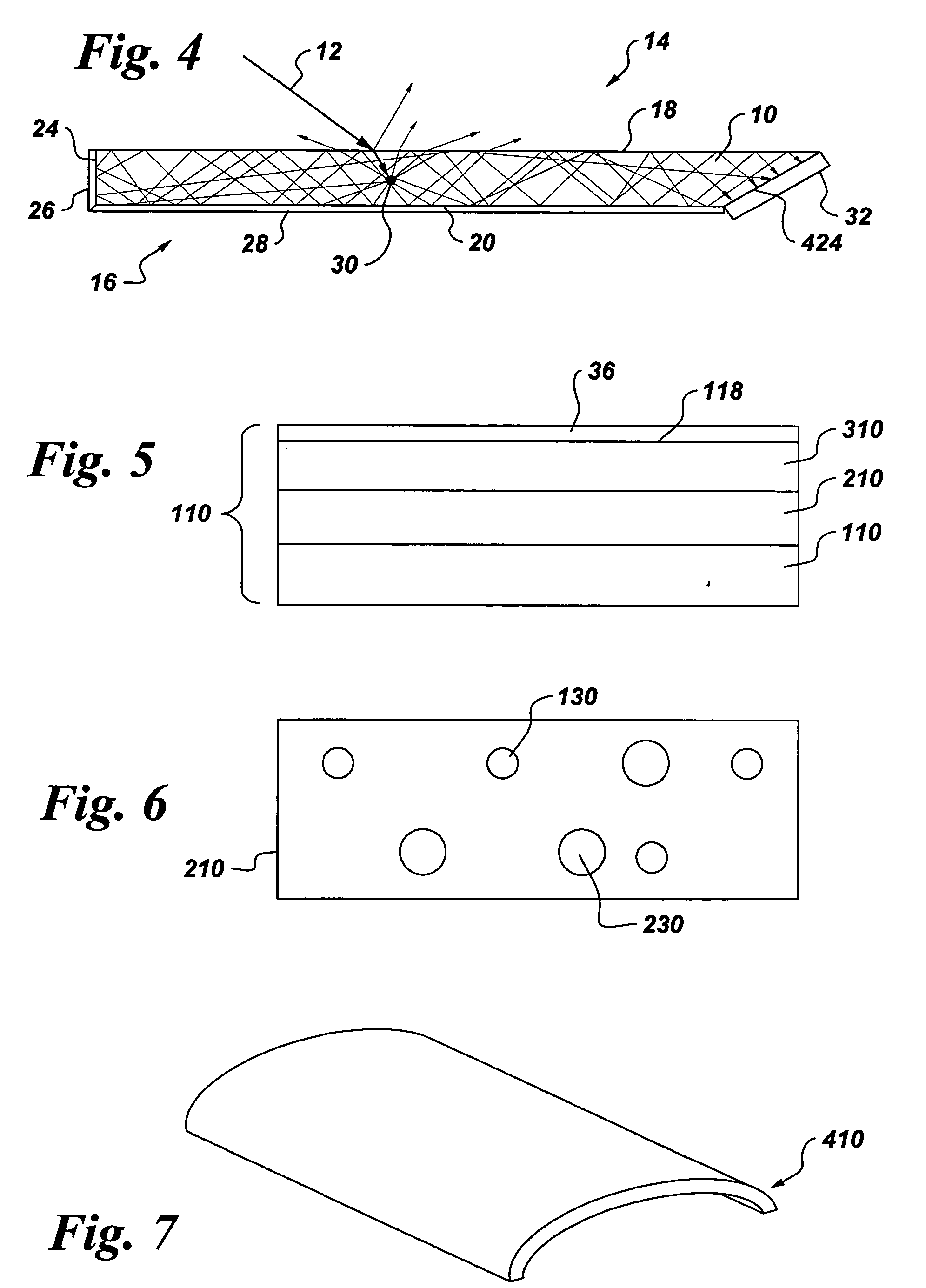
[0016]FIG. 2 is a perspective view of a building element in accordance with one embodiment of the present invention. FIG. 3 is a top view of a building element in accordance with the embodiment of FIG. 2 or various other embodiments of the present invention, and FIG. 4 is a sectional side view of a particle in a building element (including one possible alternative for the converter mounting) in accordance with the embodiment of FIG. 2.

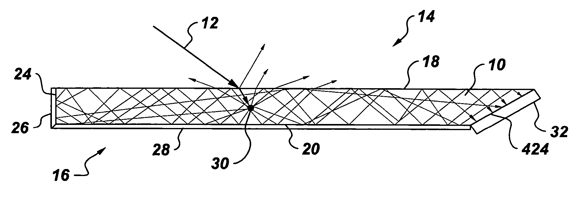
[0017] In one embodiment of the present invention, a building element 14 (FIG. 4) comprises a fluorescence collector 16. Fluorescence collector 16 includes a substrate 10 and particles 30 dispersed in substrate 10 to absorb light 12 from a plurality of directions. The absorbed light typically is emitted with a Stockes shift (a shift towards higher wavelengths). Fluorescence collector 16 has opposing surfaces 18 and 20 and a connect...


PUM


Abstract

A building element such as a roof tile, window pane, or building façade element includes a fluorescence collector comprising a substrate and particles dispersed in the substrate to absorb light from a plurality of directions and radiate the absorbed light. The fluorescence collector has opposing surfaces and a connecting surface between the opposing surfaces. A solar energy converter is configured for receiving radiated light from the fluorescence collector.

Description

BACKGROUND [0001] The invention relates generally to building elements such as roof tiles, window panes, and building facades and more specifically to building elements having solar energy converters included therein. [0002] Solar energy converters, such as photovoltaic or thermal converters, typically have high material cost, high installation cost and thus a high cost of energy (cost per kWh). One approach to reduce the material cost is to concentrate solar irradiation (focus light) onto an energy converter by means complex optical surface structuring, such as by a Fresnel lens. Such approaches are difficult to implement and have had difficulty in penetrating the renewable energy market. BRIEF DESCRIPTION [0003] Briefly, in accordance with one embodiment of the present invention, a building element comprises a fluorescence collector comprising a substrate and particles dispersed in the substrate to absorb light from a plurality of directions and radiate the absorbed light. The flu...

Claims


Application Information

Patent Timeline
IPC IPC(8): H01L25/00F24S23/00
CPCB82Y10/00F24J2/065H01L31/055Y02B10/12H02S20/25Y02B10/20Y02E10/40Y02E10/52Y02B10/14F24S23/11Y02B10/10
Inventor WILHELM KROKOSZINSKI, HANS-JOACHIM GUNTERSTROMBERGER, JOERG HERMANNMAYER, OLIVER GERHARD
Owner GENERAL ELECTRIC CO
Why Eureka
Try Eureka