Hammer drill having switching mechanism for switching operation modes

Active Publication Date: 2006-05-25
HITACHI KOKI CO LTD
View PDF11 Cites 22 Cited by
  • Summary
  • Abstract
  • Description
  • Claims
  • Application Information

AI Technical Summary

Benefits of technology

[0008] In view of the foregoing, it is an object of the present invention to provide a hammer drill that enables the user to safely replace the working tool and adjust the angle of the working tool.

Problems solved by technology

Hence, the user cannot replace the working tool or adjust the angle of the working tool if the power switch is turned on during this time since the striking force is applied to the working tool.

Method used


Image

  • Hammer drill having switching mechanism for switching operation modes
  • Hammer drill having switching mechanism for switching operation modes
  • Hammer drill having switching mechanism for switching operation modes

Examples


first embodiment

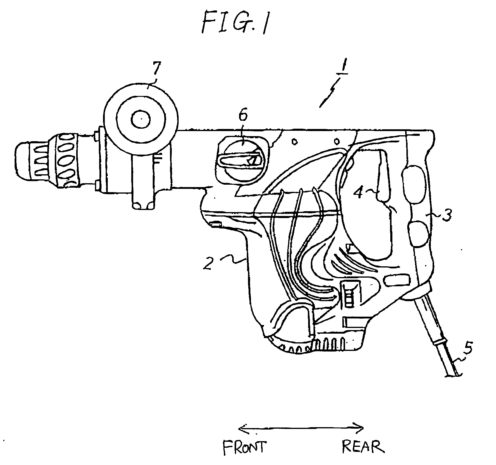
[0025]FIG. 1 is a side view of a hammer drill 1 according to a first embodiment of the present invention. The hammer drill 1 shown in FIG. 1 can operate in four operation modes: a rotation and strike mode, a rotation only mode, a strike only mode, and a neutral mode. The hammer drill 1 includes a housing 2 for housing a striking force transmitting mechanism, a rotational force transmitting mechanism, and a switching mechanism described later.

[0026] The hammer drill 1 includes a handle 3 provided on the rear end of the housing 2 (the right end in FIG. 1); an ON / OFF switch 4 provided on the handle 3; an electric cord 5 connected to the handle 3 for supplying electricity to the hammer drill 1; a dial type switching member 6 rotatably disposed on a side of the housing 2 for switching operation modes; and a sub-handle 7 disposed near the front end of the housing 2 and protruding laterally (toward the viewer in FIG. 1).

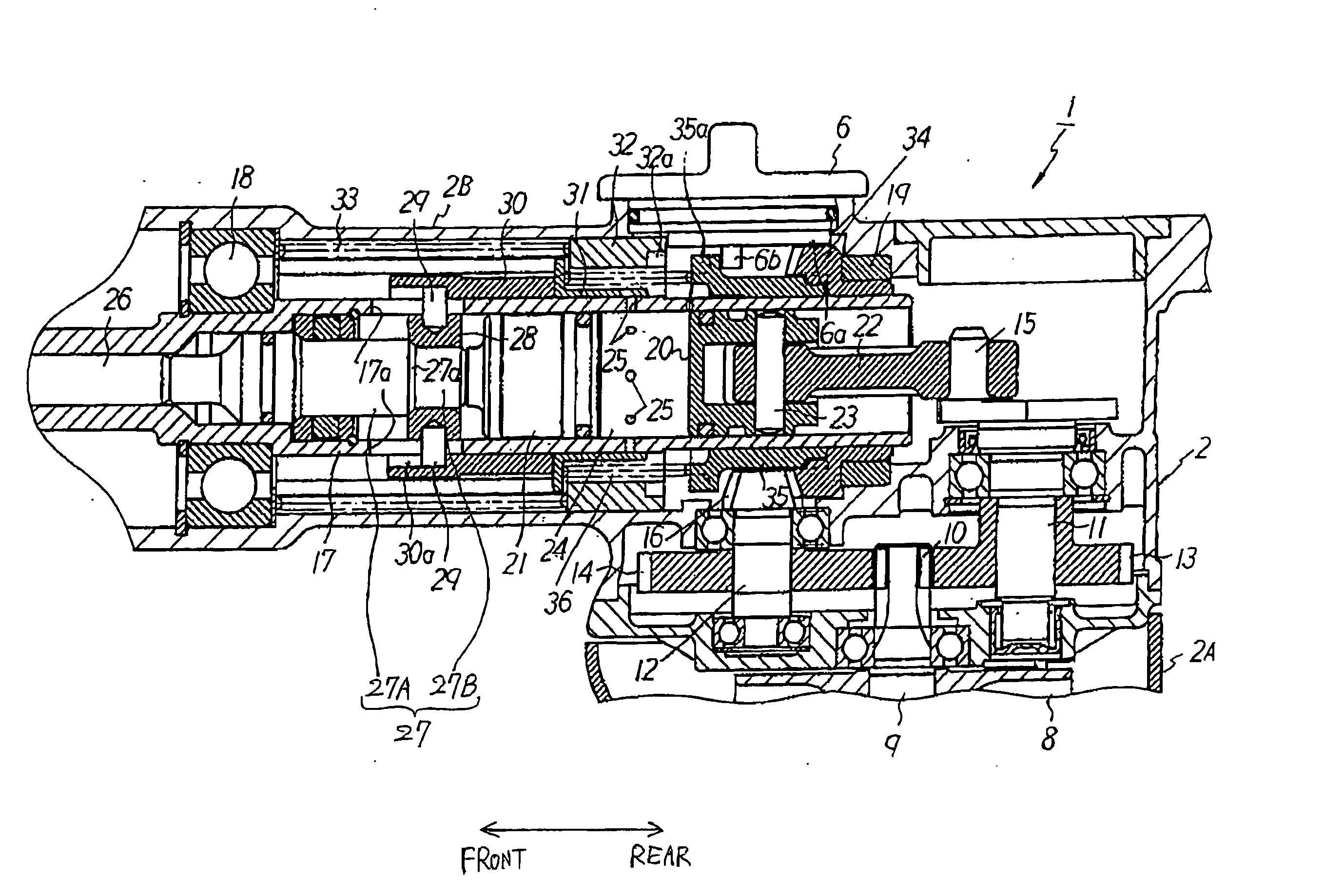
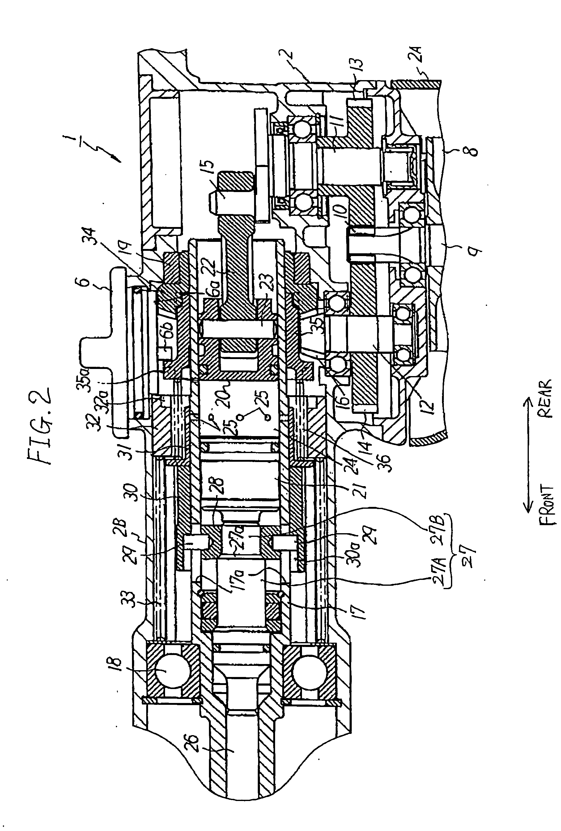
[0027] A working tool 26 (see FIG. 2) described later is mounted on ...

second embodiment

[0072] Next, a hammer drill according to a second embodiment of the present invention will be described with reference to FIGS. 11 and 12.

[0073]FIG. 11 is a vertical cross-sectional view of a hammer drill 101 according to the second embodiment in the rotation only mode, and FIG. 12 is a vertical cross-sectional view of the hammer drill 101 according to the second embodiment in the rotation and strike mode, wherein like parts and components are designated with the same reference numerals to avoid duplicating description.

[0074] In the hammer drill 101 according to the second embodiment, a cylinder 117 is held so as to be capable of moving in the front-to-rear direction. The bevel gear 34 is fitted, by spline fitting, around the outer periphery of the cylinder 117 on the rear end thereof, and the cylinder 117 can move forward and rearward relative to the bevel gear 34. The cylinder 117 rotates together with the bevel gear 34. In the present embodiment, the working tool 26 is mounted ...


PUM

PropertyMeasurementUnit
Forceaaaaaaaaaa

Abstract

A switching mechanism switches on and off transmission of a striking force to a working tool, and switches on and off transmission of a rotational force to the working tool, thereby switching operation modes among at least a rotation and strike mode, a strike only mode, and a neutral mode. A rotation locking mechanism engages a cylinder during the strike only mode, thereby locking rotation of the cylinder. During the neutral mode, the transmission of the striking force, the transmission of the rotational force, and the locking of rotation of the cylinder are all turned off.

Description

BACKGROUND OF THE INVENTION [0001] 1. Field of the Invention [0002] The present invention relates to a hammer drill functioning both as a hammer and as a drill and including a striking force transmitting mechanism for applying a striking force to a working tool, and a rotational force transmitting mechanism for transmitting a rotational force to the working tool. [0003] 2. Description of Related Art [0004] Hammer drills provided with both a striking force transmitting mechanism and a rotational force transmitting mechanism have been conventionally provided with three operation modes: a rotation and strike mode for applying a striking force to the working tool while simultaneously driving the working tool to rotate, a rotation only mode for driving the working tool to rotate, and a strike only mode for applying a striking force to the working tool. This type of hammer drill requires an operation mode switching mechanism to switch the operation mode according to the desired operation....

Claims


Application Information

Patent Timeline
IPC IPC(8): B25D11/00
CPCB25D11/005B25D11/125B25D16/006B25D2211/003B25D2211/068B25D2216/0015B25D2216/0023B25D2216/0038B25D2216/0046B25D2216/0069B25D2250/035B25D2250/131B25D2250/241
Inventor YAMAZAKI, SHINGO
Owner HITACHI KOKI CO LTD
Why Eureka
Try Eureka