
Device and method for head restraint

a head restraint and head support technology, applied in the field of head restraint devices and methods, can solve the problems of inconvenience for travelers, difficulty in obtaining adequate neck and head support, and pain for travelers, and achieve the effect of reducing snoring and other undesirable sleep related activities

Inactive Publication Date: 2006-05-25
MILLER SCOTT D
View PDF0 Cites 18 Cited by
  • Summary
  • Abstract
  • Description
  • Claims
  • Application Information

AI Technical Summary

Benefits of technology

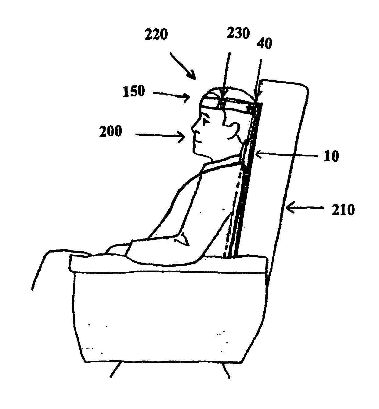
The device effectively stabilizes the head and neck, reducing muscular stress, facilitating proper breathing, and minimizing snoring, while being unobtrusive and adaptable for various sleeping positions without interfering with others.

Problems solved by technology

Travelers who are forced to sit for a period of time in an upright posture have long struggled with obtaining adequate neck and head support to ensure comfort.
Particularly during travel in, for example, airplanes, cars / buses, or trains, a traveler may wish to sleep and this may prove difficult without adequate head support.
However, head movement, particularly in the forward direction, may make sleep impossible or, at the very least, painful for some travelers.
Complicating the problem are various safety and space issues, particularly on airplanes, that limit the types of devices available to the traveler.
However, while the travel pillows disclosed in the art provide some neck support, particularly in the side to side range of movement, the pillows provide poor support in stopping forward movement of the head and in generally keeping the head aligned with the spine.
Such movement may be quite common in moving vehicles and may result in discomfort for the user.
However, this device also does not support the users head from forwardly moving.
However, this apparatus is cumbersome and uncomfortable and does not provide full support in the forward direction.
However, these devices do not provide support in the forward direction.
Particularly on airplanes, this is problematic because, for example, the straps or securing devices are clumsy and may entangle other passengers (particularly in an emergency situation).
Further, the user may have difficulty releasing himself from the straps.
Further, the straps or other apparatus for providing a secure surface may interfere with the passenger directly behind the user (for example, the strap may interfere with the entertainment screen which is often located on the seatback).
However, the device does not, for example, provide head / neck support in the forward direction.
However, the device does not provide head / neck support in the forward direction.
However, in addition to the many obvious drawbacks of this device, the downward pressure it creates on the neck of the user may become uncomfortable.
However the device has several drawbacks.
The device is clumsy and blocks the peripheral sight of the user.
Further, the device is not suited for use in alternative sleeping positions such as against the corner where a seat meets a wall.
Further, the device is not practical for use when the user wishes to turn their head to the side.
Further, the connecting apparatus cannot be made integral to the support apparatus.
Further, the user's head would have a tendency to bounce against the restraining bar.
Further, the device does not secure the head in a position that correctly aligns the head with the spine.
However, the device is cumbersome and fails to provide the neck support of the instant invention.
Other serious deficiencies may also be present.
Furthermore, none of these disclosures teach or suggest the advantages of the instant invention and none of the disclosed devices comprise the advantages of the instant invention.

Method used


Image

  • Device and method for head restraint
  • Device and method for head restraint
  • Device and method for head restraint

Examples


example 1

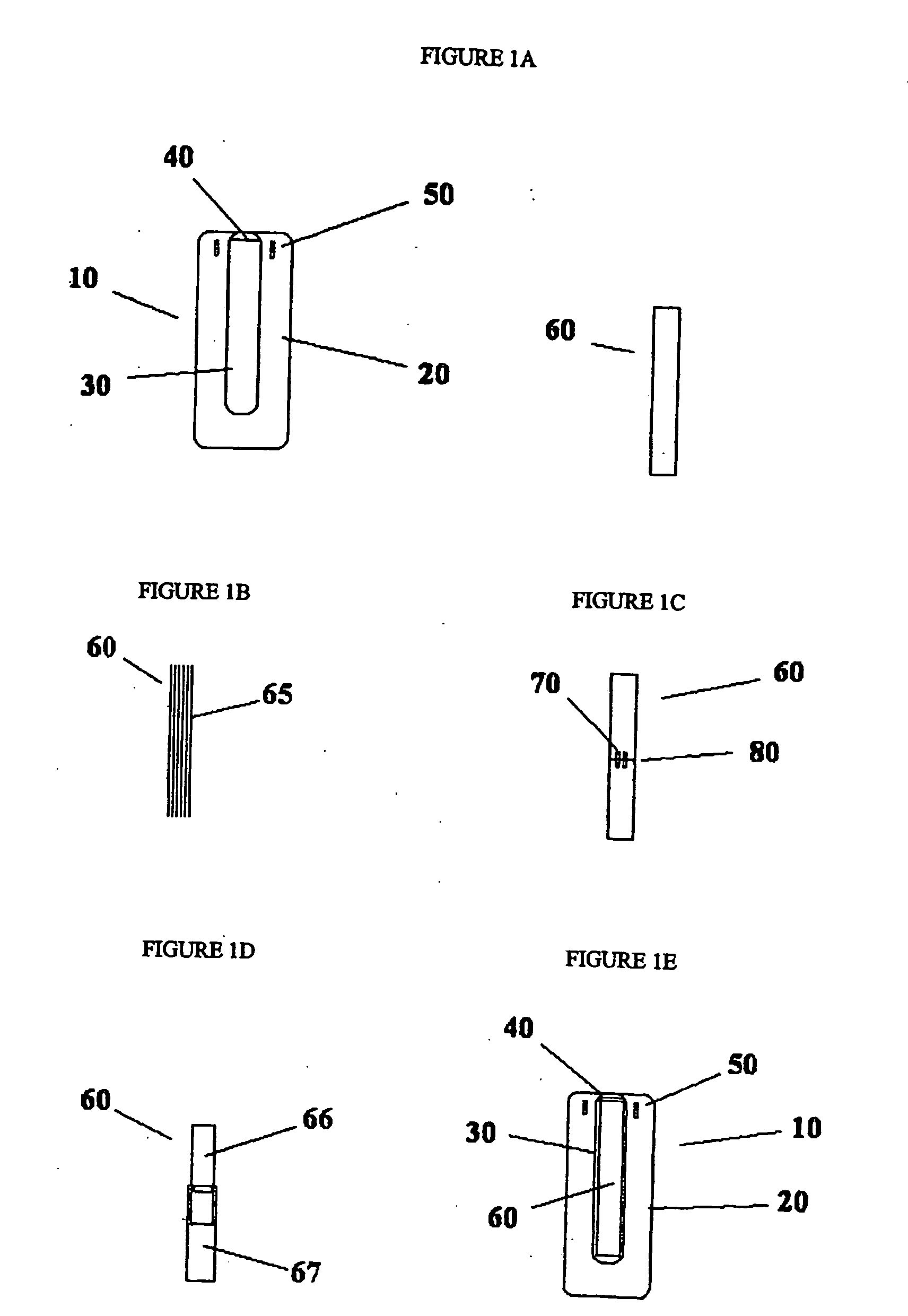
[0099] A rigid support comprising ⅛th inch thick acrylic was fabricated to be 4 inches wide and 16 inches long. The support was covered with two layers of 3mm neoprene. The attachment apparatus was fabricated by gluing a 3-inch wide strip of neoprene to the back of the support at the upward portion to form a “belt-loop” structure. The securing apparatus was made by first cutting a strip of sailcloth approximately 2 inches wide and 24 inches long. Velcro was affixed to the ends. The strip was cut in half in the middle and a 2-inch piece of elastic was attached to connect the two pieces back together. A headpiece / eye mask was fabricated from fleece such that the strip of sailcloth could be threaded through the headpiece where it meets the user's forehead. The eye mask portion can be folded up or down when the device is in use.

[0100] The sailcloth was threaded through the “belt loop” on the back of the support device and the ends were attached by the Velcro such that the securing appa...

example 2

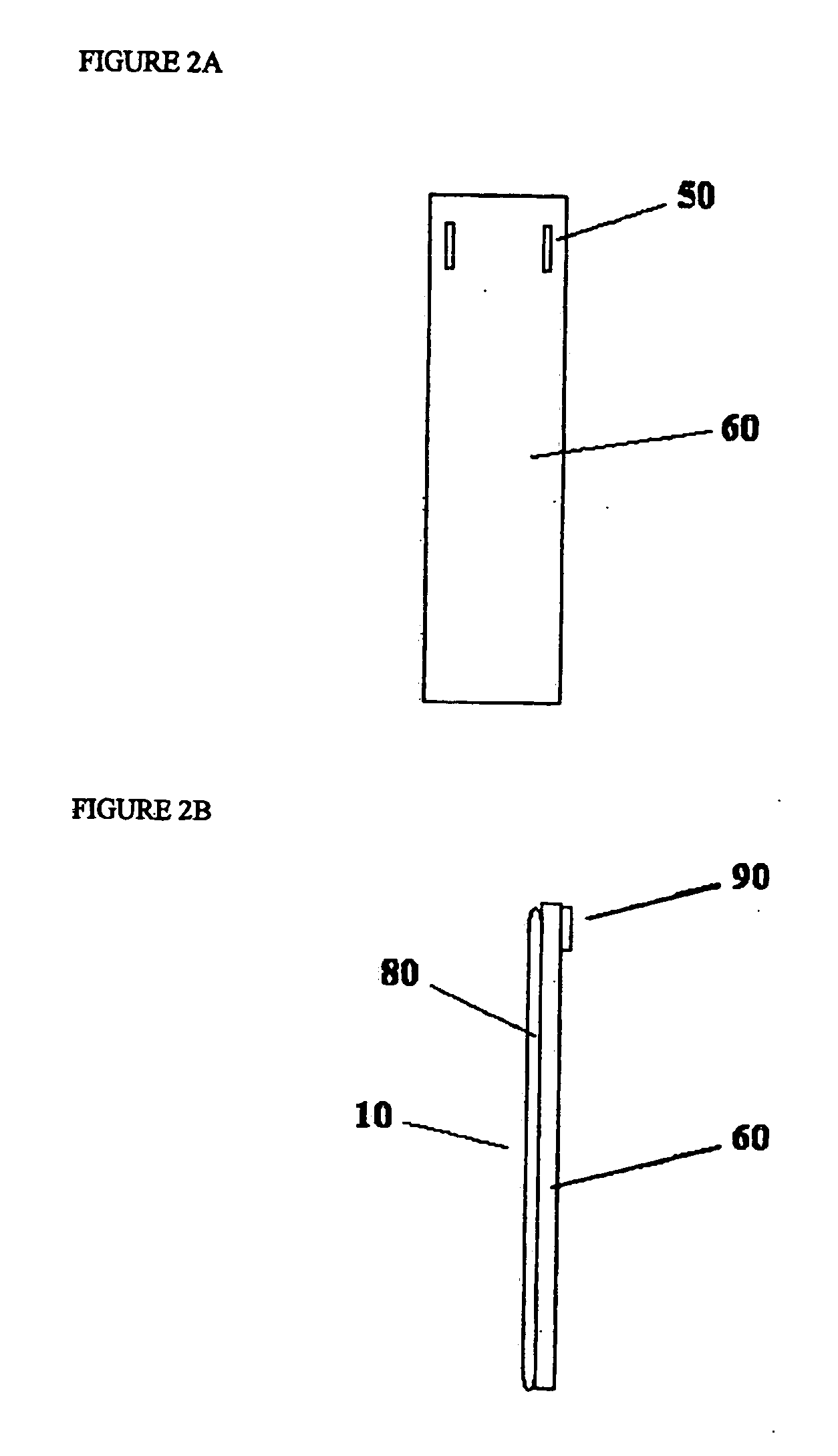
[0101] A rigid support consisting of ⅛th inch thick acrylic was fabricated to be 4 inches wide and 12 inches long. A support cover was fabricated of nylon and fleece with a pocket sized to fit the acrylic support. The support cover extended 4 inches below the bottom of the rigid support when the rigid support was placed in the support cover pocket. The attachment apparatus was fabricated by putting slots on either side of the top of the cover piece such that the securing apparatus could be threaded through the slots. The securing apparatus was made by first cutting a strip of sailcloth approximately 2 inches wide and 24 inches long. Velcro was affixed to the ends. The strip was cut in half in the middle and a 2-inch piece of elastic was attached to connect the two pieces back together. A headpiece / eye mask was fabricated from fleece such that the strip of sailcloth could be threaded through the headpiece where it meets the user's forehead. The eye mask portion can be folded up or do...

example 3

[0103] A rigid support consisting of 4⅛th inch thick acrylic pieces was glued to a piece of neoprene approximately 8 inches wide. The pieces were spaced according to FIG. 11. A second piece of neoprene, identical in size to the first piece, was glued such that a sandwich was created with the rigid support disposed in between the two neoprene pieces. The attachment apparatus was fabricated by cutting slots through the neoprene near the top such that the securing apparatus could be threaded through the slots. The securing apparatus was made by first cutting a strip of sailcloth approximately 2 inches wide and 24 inches long. Velcro was affixed to the ends. The strip was cut in half in the middle and a 2-inch piece of elastic was attached to connect the two pieces back together. A headpiece / eye mask was fabricated from fleece such that the strip of sailcloth could be threaded through the headpiece where it meets the user's forehead. The eye mask portion can be folded up or down when th...


PUM


Abstract

Disclosed is a device capable of supporting a user's head when the user is seated in an upright position. The present invention includes a head support device comprising a support apparatus capable of fitting comfortably between a user's back and a seat surface and a securing apparatus capable of holding the user's head, wherein the support apparatus provides a rigid or semi-rigid support when fitted between the user and the seat surface and the securing apparatus is capable of securing the user's head to the support apparatus.

Description

CROSS REFERENCE TO RELATED APPLICATIONS [0001] This application claims the priority of U.S. patent application Ser. No. 10 / 855,062, filed May 26, 2004, U.S. Patent Application Ser. No. 60 / 475,752, filed Jun. 4, 2003, and U.S. Patent Application Ser. No. 60 / 505,771, filed Sep. 24, 2003, each hereby incorporated by reference in their entirety.STATEMENT REGARDING FEDERALLY SPONSORED RESEARCH OR DEVELOPMENT [0002] Not applicable. REFERENCE TO A SEQUENCE LISTING [0003] Not applicable. BACKGROUND OF THE INVENTION [0004] 1. Field of the Invention [0005] This invention relates to devices and methods that provide support for the head, neck and upper spine. In a preferred embodiment, the invention relates to devices and methods that will facilitate sleep or general comfort during travel or other activities that are performed in an upright or seated position. [0006] 2. Description of the Related Art [0007] Travelers who are forced to sit for a period of time in an upright posture have long str...

Claims


Application Information

Patent Timeline
Patent Type & Authority Applications(United States)
IPC IPC(8): A47C1/10A47C7/38A47C16/00
CPCA47C7/383
Inventor MILLER, SCOTT D.
Owner MILLER SCOTT D
Learn More