This helps you quickly interpret patents by identifying the three key elements:
Problems solved by technology
Method used
Benefits of technology
Benefits of technology
[0010] An object of the present invention is to provide a rotor for a line-start reluctance motor which reduces time and expenses in production by using simple elements.
[0012] Yet another object of the present invention is to provide a rotor for a line-start reluctance motor which has high outputs and efficiency, by maximizing a difference between flux density in a high permeable direction and flux density in a low permeable direction.
[0013] Yet another object of the present invention is to provide a rotor for a line-start reluctance motor which has efficient start properties by changing shapes and alignments of bars.
Problems solved by technology
As described above, the conventional rotors have a number of complicated elements, which consumes a lot of time and expenses during the production.
The conventional arts do not provide maximum outputs and efficiency of the rotor based on a difference between flux density in a high permeable direction (for example, d axis) and flux density in a low permeable direction (for example, q axis).
Furthermore, the conventional arts do not provide shapes and alignments of bars for giving efficient output properties to the rotor by preventing magnetic saturation in the core.
Method used
Image
Click on the blue label to locate the original text in one second.
Reading with bidirectional positioning of images and text.
Examples
first embodiment
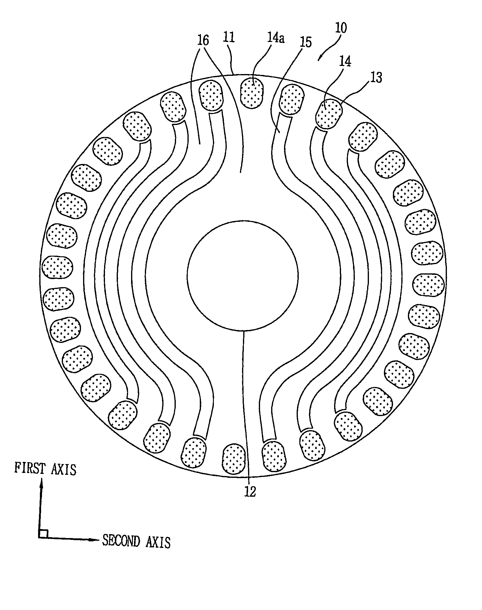
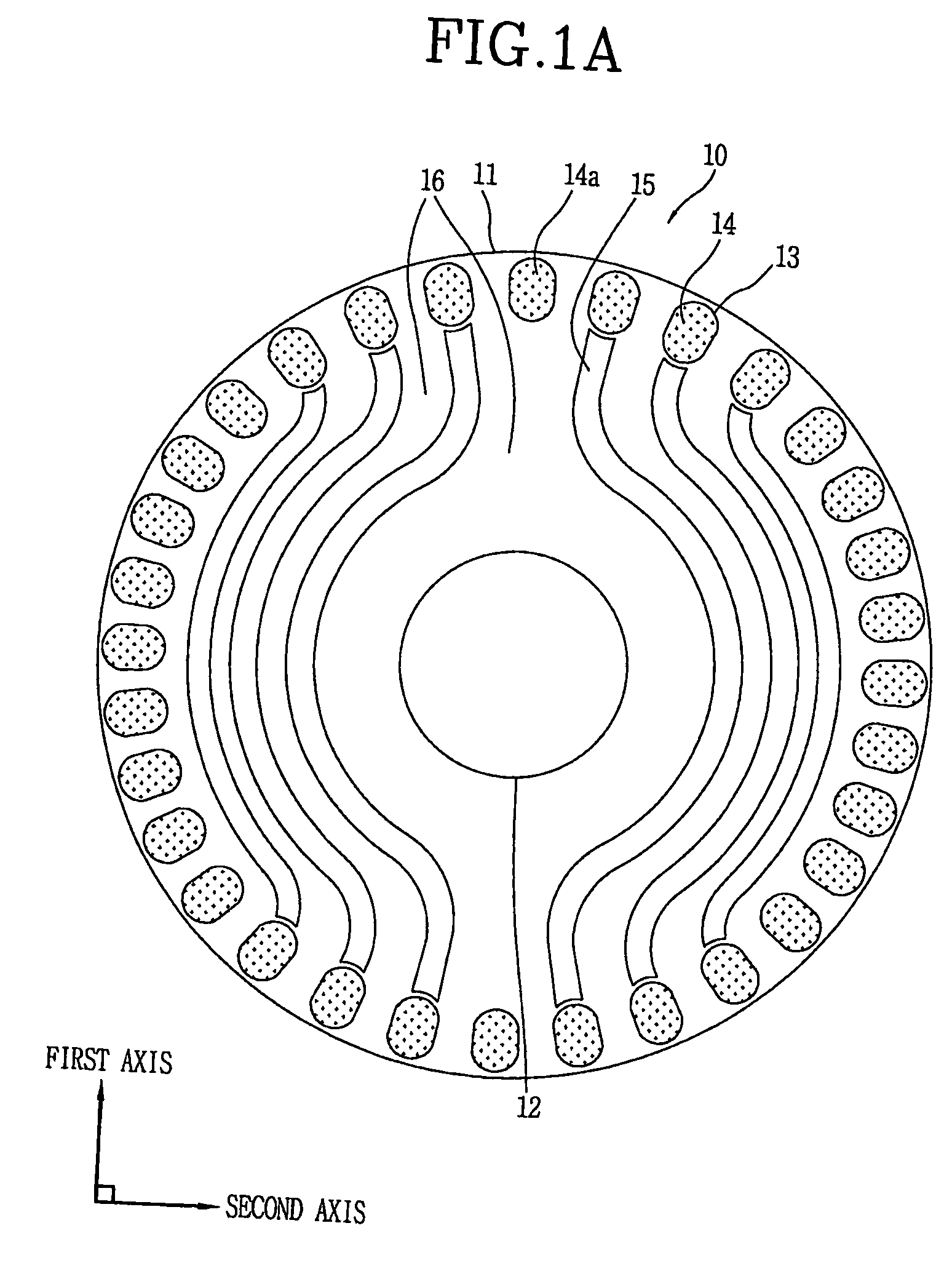
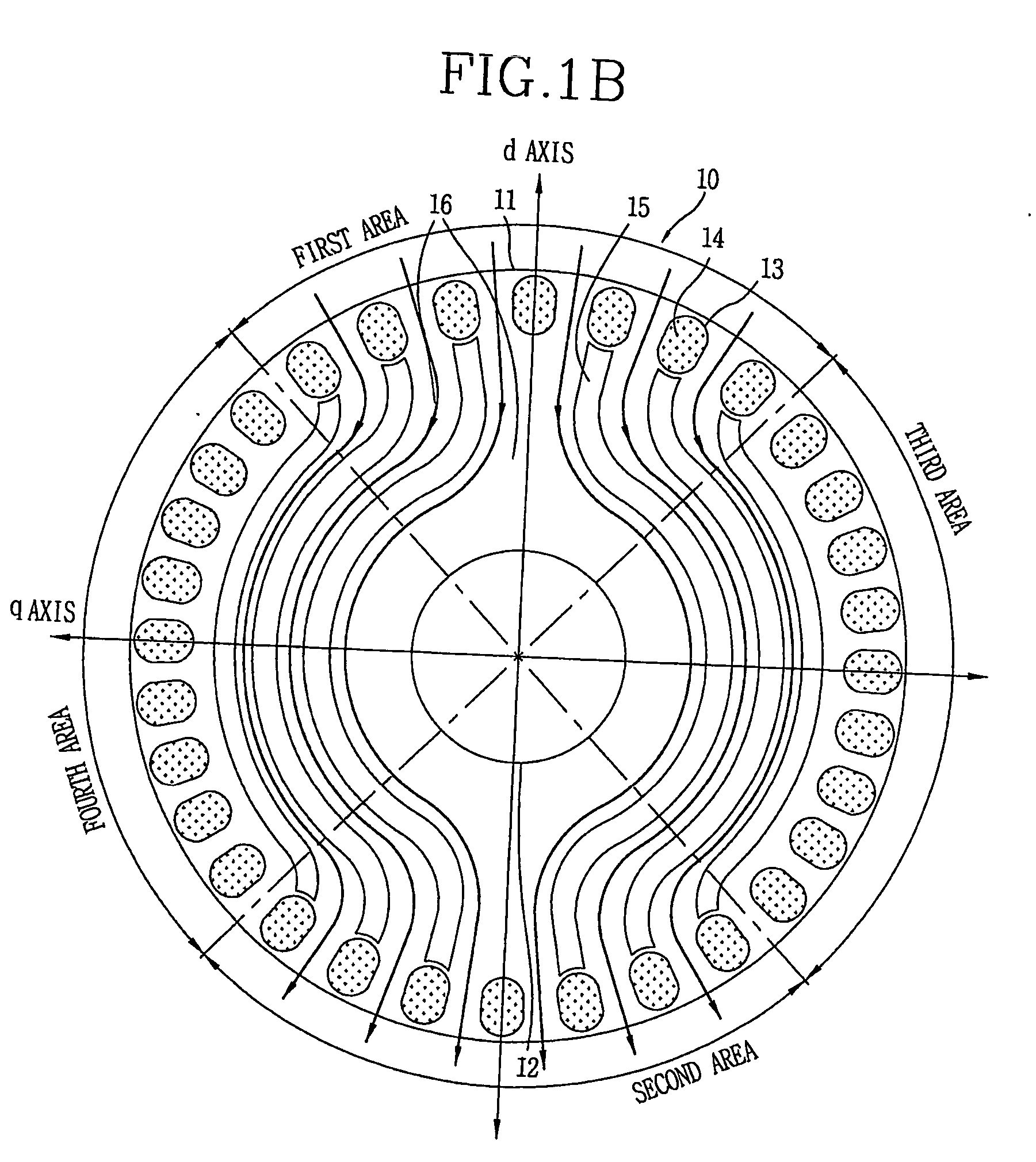
[0046]FIGS. 1A and 1B are plane views illustrating a rotor for a line-start reluctance motor in accordance with the present invention.
[0047] Referring to FIG. 1A, a rotor 10 includes a core 11 having an axis coupling hole 12 formed in a coupling direction of a shaft (not shown). The core 11 includes a plurality of bar insertion holes 13 in its periphery, and a plurality of bars 14 are inserted into the bar insertion holes 13. In addition, the core 11 has a plurality of flux barriers 15 extending toward a first axis vertical to the coupling direction of the shaft (hereinafter, referred to as ‘coupling direction’), and being symmetric to each other on a second axis vertical to the first axis. Parts of the core 11 between the plurality of flux barriers 15 which flux flows through are flux paths 16.
[0048] In detail, the rotor 10 is comprised of a plurality of stacked core planes, and the core 11 does not require special magnetic materials.
[0049] The bars 14 are inserted into the bar i...
second embodiment
[0062]FIGS. 2A and 2B are plane views illustrating a rotor for a line-start reluctance motor in accordance with the present invention. The rotor 20 of FIG. 2A has the aforementioned properties of the rotor 10 of FIG. 1A, and also has additional properties described below.
[0063] As shown in FIG. 2A, flux enters the rotor 20 in the d axis direction and flows through flux paths 26, but rarely flows in the q axis direction. The detailed explanation of the rotor 20 will later be explained with reference to FIG. 2B.
[0064] Still referring to FIG. 2A, as identical to the rotor 10 of FIG. 1A, the rotor 20 is divided into first and second areas facing each other at a predetermined angle α on a central line of d axis on a core plane vertical to a coupling direction, and also be divided into third and fourth areas between the first and second areas. In consideration of a start force of the rotor 20, the angle α is preferably 100 to 110°, more preferably, 104 .
[0065] The rotor 20 is provided w...
third embodiment
[0072]FIG. 3 is a plane view illustrating a rotor for a line-start reluctance motor in accordance with the present invention. The rotor 30 of FIG. 3 has the whole properties of the rotor 10 of FIG. 1A and some properties of the rotor 20 of FIG. 2 (for example, except the flux barrier 25a), and also has additional properties.
[0073] In detail, in a core 31 of the rotor 30, bars 34 in third and fourth areas are installed in flux barriers 35a. That is, the flux barriers 35a are formed between the bars 34 in the third and fourth areas. Flux entering between the bars 34 do not flow into the core 31 due to the flux barriers 35a. Therefore, a difference between flux density on d axis and flux density on q axis considerably increases.
PUM
Abstract
The present invention discloses a rotor for a line-start reluctance motor which improves core area efficiency to make flux flow in one direction. The rotor for the line-start reluctance motor includes a core having an axis coupling hole in a coupling direction of a shaft, a plurality of bars formed in the periphery of the core, and a plurality of flux barriers, one and the other ends of the flux barriers approaching the bars formed in first and second areas facing each other at a predetermined angle on a central line of a first axis on a core plane vertical to the coupling direction, at least parts of the centers of the flux barriers passing through a third or fourth area between the first and second areas, surrounding the axis coupling hole at predetermined intervals.
Description
TECHNICAL FIELD [0001] The present invention relates to a rotor for a line-start reluctance motor, and more particularly to, a rotor for a line-start reluctance motor which improves core area efficiency to make flux flow in one direction. BACKGROUND ART [0002] A line-start reluctance motor is a single phase power alternating motor for performing constant speed motion. It is a combination type of an induction motor and a reluctance motor. The line-start reluctance motor includes a stator for forming a rotating magnetic field by alternating current applied to windings, and a rotor positioned in the stator and rotated by the rotating magnetic field formed by the stator. The line-start reluctance motor uses a rotary force generated when flux of the stator passes through the rotor and the rotor moves in a direction of decreasing reluctance (magnetic resistance). That is, in the start operation, the line-start reluctance motor starts to be rotated by using start torque generated by mutual...
Claims
Application Information
Patent Timeline
Application Date:The date an application was filed.
Publication Date:The date a patent or application was officially published.
First Publication Date:The earliest publication date of a patent with the same application number.
Issue Date:Publication date of the patent grant document.
PCT Entry Date:The Entry date of PCT National Phase.
Estimated Expiry Date:The statutory expiry date of a patent right according to the Patent Law, and it is the longest term of protection that the patent right can achieve without the termination of the patent right due to other reasons(Term extension factor has been taken into account ).
Invalid Date:Actual expiry date is based on effective date or publication date of legal transaction data of invalid patent.

