Light source device and projection display apparatus

a technology of projection display and light source device, which is applied in the direction of lighting and heating apparatus, instruments, transportation and packaging, etc., can solve the problems of projector itself becoming unduly large in size, affecting the cooling effect, and unable to efficiently discharge cooling air, so as to reduce the cooling effect and prevent the scattered out of broken pieces of lamps

Inactive Publication Date: 2006-05-25
NEC DISPLAY SOLUTIONS LTD
View PDF9 Cites 14 Cited by
  • Summary
  • Abstract
  • Description
  • Claims
  • Application Information

AI Technical Summary

Benefits of technology

[0009] It is an object of the present invention to provide a light source device and a projection display apparatus which have a structure for reliably preventing broken pieces of a lamp from bei...

Problems solved by technology

When they are burst, they are liable to release energy large enough to deform the metal lamp house which houses the xenon lamp therein.
The conventional proposal to use a longer outlet duct with metal mesh filters disposed therein is disadvantageou...

Method used


Image

  • Light source device and projection display apparatus
  • Light source device and projection display apparatus
  • Light source device and projection display apparatus

Examples


1st embodiment

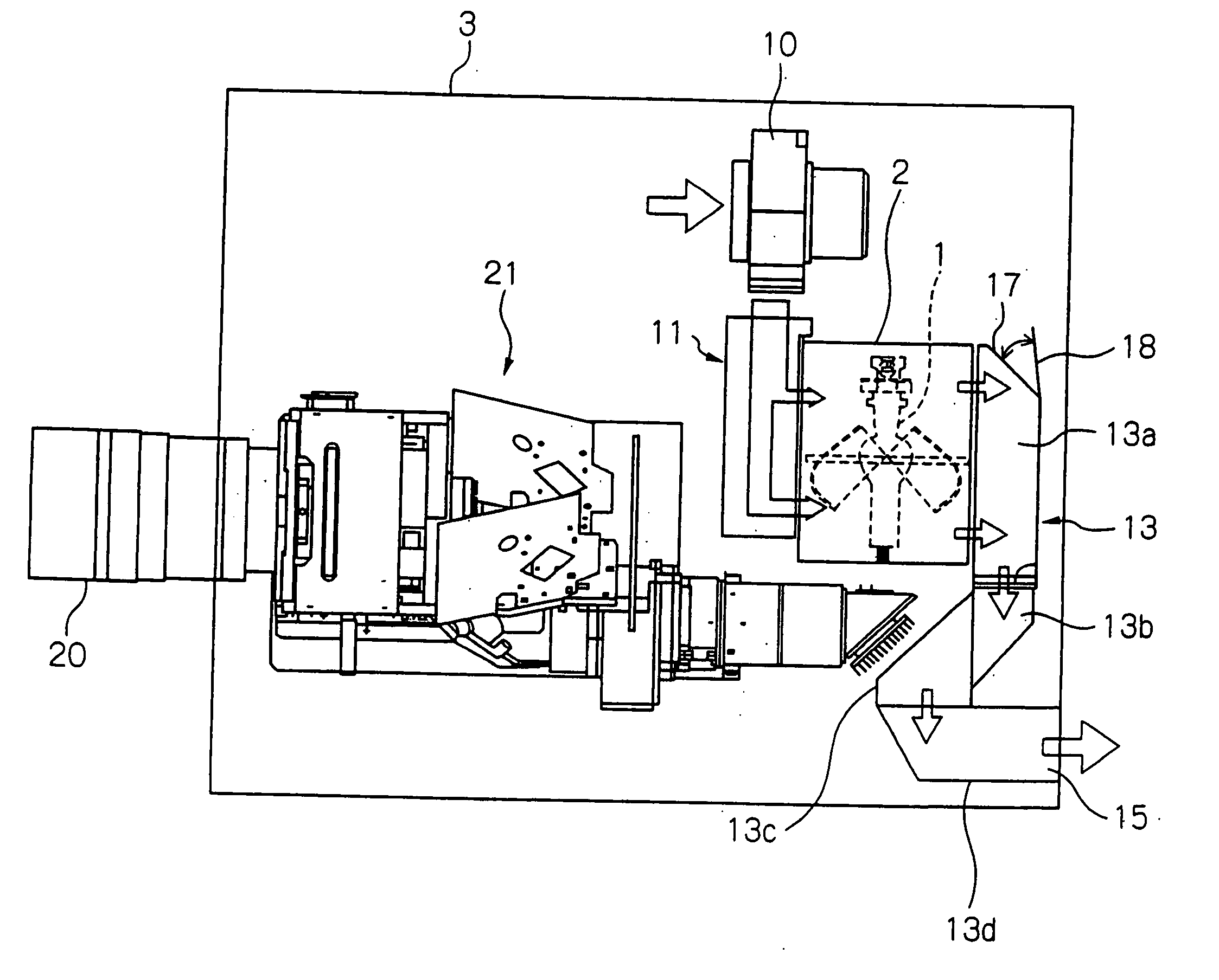
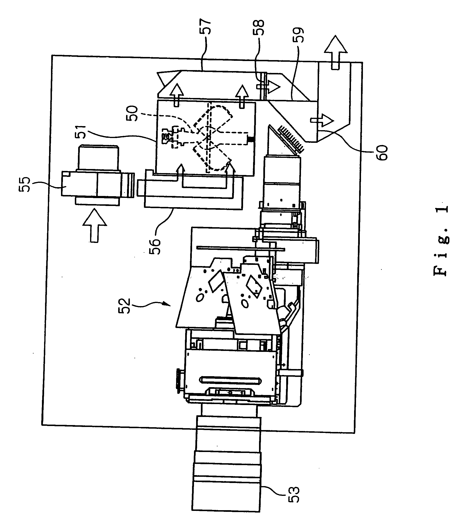
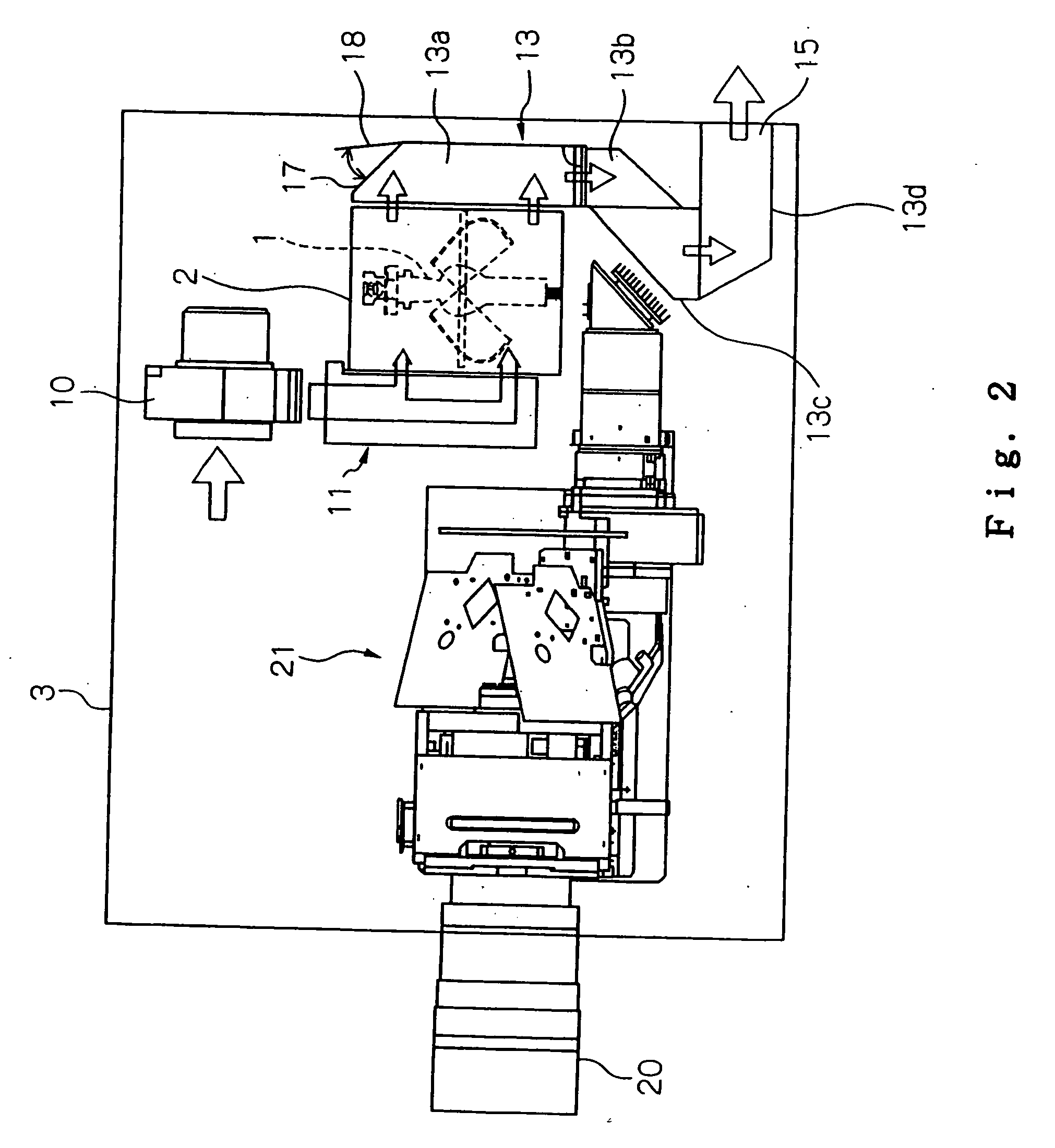
[0024] A projection display apparatus according to a first embodiment of the present invention is a DLP projector having DMDs (Digital Micromirror Devices) as image forming devices (light valves). FIG. 2 shows in schematic plan the projection display apparatus according to the first embodiment of the present invention. FIG. 3 shows in enlarged cross section a lamp house and nearby components of the projection display apparatus shown in FIG. 2. FIG. 4 shows in enlarged perspective a part of first duct member of the projection display apparatus shown in FIG. 2.

[0025] As shown in FIG. 2, lamp house 2 is disposed in a main housing 3 of the DLP projector, and accommodates therein xenon lamp 1 as a light source. Lamp house 2 is in the form of a metal box. Lamp house 2 houses therein a reflector for collecting and guiding light emitted from xenon lamp 1. Lamp house 2 has a window (not shown) though which the light that is guided by the reflector is projected from the lamp house 2.

[0026] ...

2nd embodiment

[0036] A projection display apparatus according to a second embodiment of the present invention is shown in FIGS. 6 and 7. The projection display apparatus according to the second embodiment is a DLP projector having basic structural details identical to those of the DLP projectors shown in FIGS. 2 and 5. Those parts shown in FIG. 6 and 7 which are identical to those shown in FIGS. 2 and 5 are denoted by identical reference characters, and will not be described in detail below.

[0037] The DLP projector according to the second embodiment differs from the DLP projector according to the first embodiment in that lamp house 2 has opening 30 and lid 31. Specifically, as shown in FIGS. 6 and 7, opening 30 is defined in side wall 32 of lamp house 2 which lies perpendicularly to side wall 5 connected to air inlet duct 11 and side wall 7 connected to air outlet duct 13. Opening 30 is omitted from illustration in FIG. 6 for the sake of brevity. Plate-like lid 31 is swingably mounted on lamp ho...


PUM


Abstract

A projection display apparatus generates image light by modulating, with an image signal, light emitted from a light source disposed in a lamp house, and projects the generated image light onto a screen. The projection display apparatus has an air inlet duct for introducing air, to cool the light source, into the lamp house and an air outlet duct for expelling the air discharged from the lamp house out of the projection display apparatus. The air outlet duct has an opening defined in a side wall thereof, and a lid pivotally mounted thereon for selectively opening and closing the opening. The lid is not opened under normal pressure in the air outlet duct when the light source operates normally, and is opened when an abnormal pressure buildup higher than the normal pressure is applied to the lid, thereby releasing the pressure buildup.

Description

BACKGROUND OF THE INVENTION [0001] 1. Field of the Invention [0002] The present invention relates to a light source device and a projection display apparatus, and more particularly to a technology for minimizing damage caused when a high-pressure discharge lamp as a light source is burst. [0003] 2. Description of the Related Art [0004] Projection display apparatus such as liquid crystal projectors and DLP (Digital Light Processing) projectors have recently been in widespread use. Generally, a projection display apparatus has a lamp as a light source, an image forming device for modulating light emitted from the lamp with an image signal, and an image optics for projecting image light that is generated by the image forming device onto a screen at an enlarged scale. [0005] One conventional DLP projector having three digital micromirror devices (DMDS) is shown in FIG. 1 of the accompanying drawings. As shown in FIG. 1, the DLP projector has a light source comprising high-pressure disch...

Claims


Application Information

Patent Timeline
IPC IPC(8): F21V29/00
CPCF21V29/02G03B21/16H04N9/3141G03B21/2026G03B21/2086F21V29/67F21V29/83
Inventor TAKEDA, MIKIYA
Owner NEC DISPLAY SOLUTIONS LTD
Why Eureka
Try Eureka