Vehicle lighting apparatus

a technology for lighting apparatuses and vehicles, applied in lighting and heating apparatus, fixed installations, cycle equipment, etc., can solve the problems of difficult to enhance the degree of freedom in designing such lighting apparatuses, difficult to design air vent holes, etc., and achieve the effect of preventing the increase in the number of parts used

Inactive Publication Date: 2006-05-25
HONDA MOTOR CO LTD
View PDF14 Cites 16 Cited by
  • Summary
  • Abstract
  • Description
  • Claims
  • Application Information

AI Technical Summary

Benefits of technology

[0010] In accordance with these arrangements, an increase in the number of parts used is prevented, as compared with the arrangement in which each of the lamps is provided with an individual lamp housing. It is also possible to let each of the high beam lamp and the low beam lamp assume an independent appearance. It should be noted that placing the high beam lamp on the upper portion and the low beam lamp on the lower portion is advantageous in illuminating a remote distance with the high beam lamp or a road surface immediately ahead of the vehicle with the low beam lamp.
[0011] In the present invention, a lens for the low beam lamp is narrower vertically and wider horizontally. A wide range of a road surface forward of the vehicle in the lateral direction can therefore be illuminated, while widening of an illumination light in the vertical direction in a low beam mode can be suppressed.
[0012] In the present invention, a lens for the high beam lamp is disposed at a central portion of the cowling and is circular in a front view thereof. This arrangement makes it easier to distribute an illumination light of the high beam lamp toward a remote distance.

Problems solved by technology

However, this particular configuration hampers emphasizing the shape of each individual lens and the shape of each individual lamp.
Thus, it is difficult to enhance a degree of freedom in designing such a lighting apparatus.
However, in an effort to ensure good ventilation, enlarging the air vent hole or increasing the number of the air vent holes, makes it difficult to design the air vent hole.
Similarly, making the air vent pipe project outside the lamp housing contributes to a complicated housing structure.

Method used


Image

  • Vehicle lighting apparatus
  • Vehicle lighting apparatus
  • Vehicle lighting apparatus

Examples


first embodiment

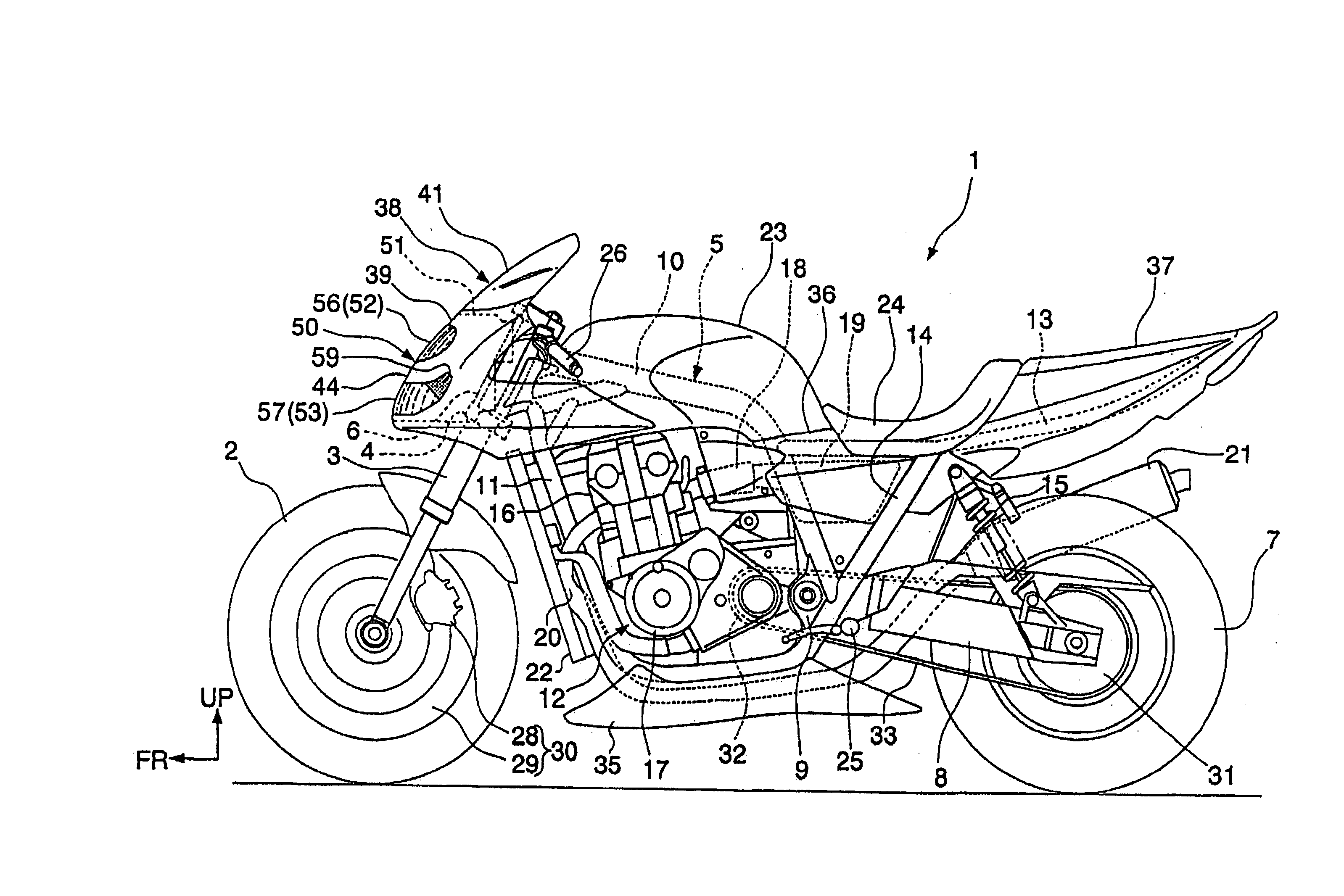
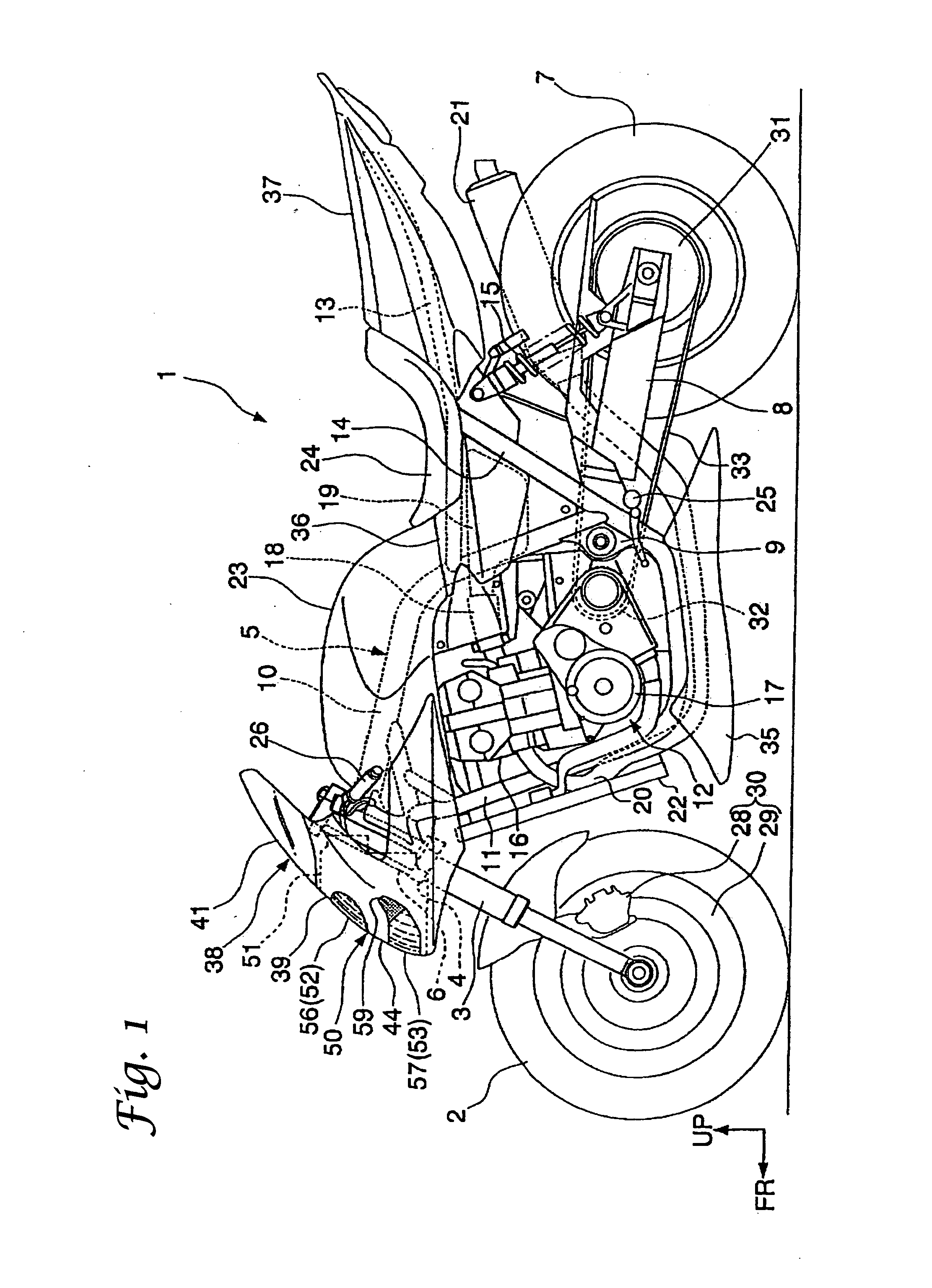
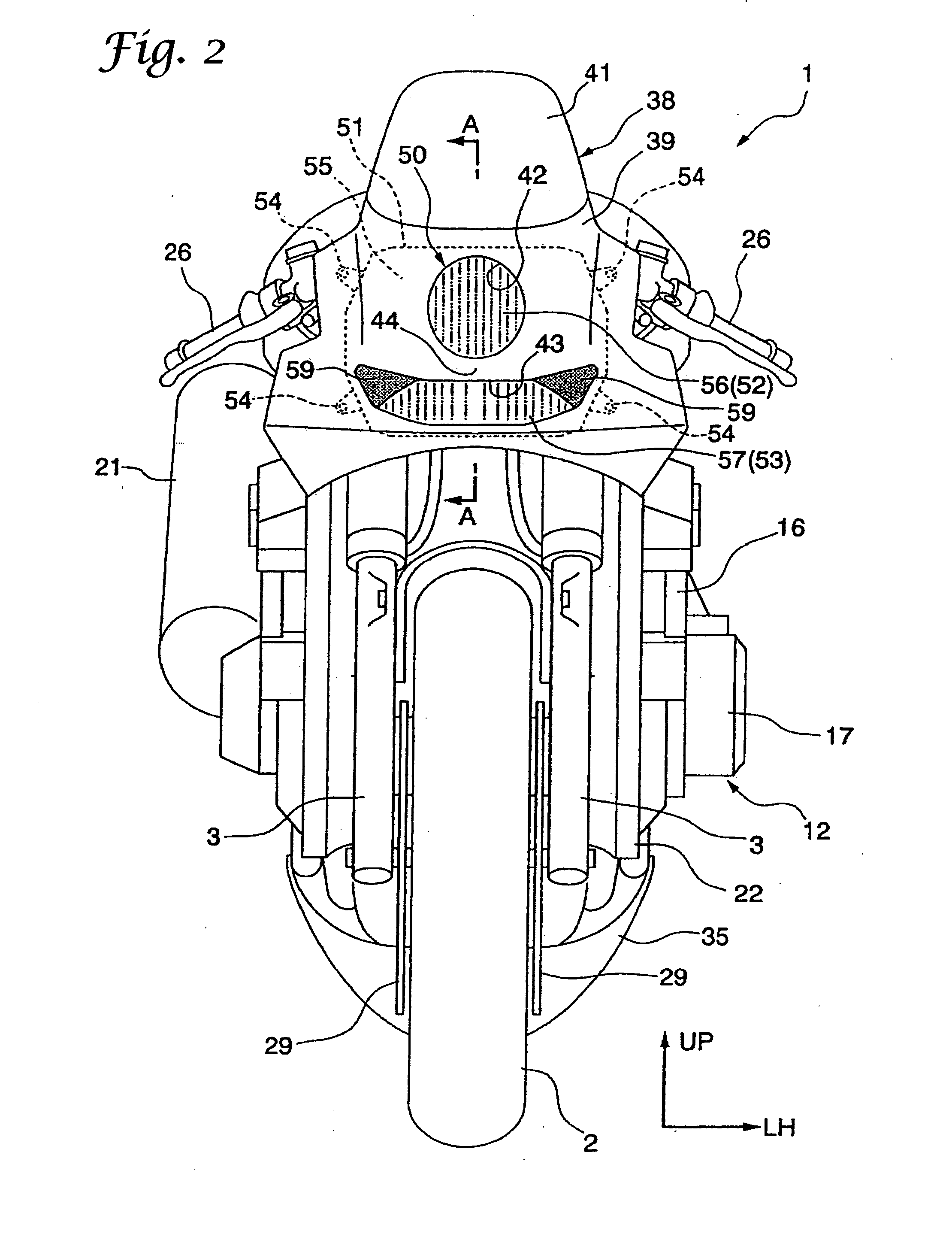
[0063] As described in the foregoing, the headlamp unit 50 according to the present invention includes the high beam lamp 52 and the low beam lamp 53 arranged vertically. The high beam lamp 52 is positioned on the upper portion, while the low beam lamp 53 is positioned on the lower portion. Further, the headlamp unit 50 has part of the front cowl 38 (the lamp to lamp transverse portion 44) covering the area between the two lamps 52, 53.

[0064] According to these arrangements, a minimum number of parts are used, as compared with an arrangement in which each of the lamps 52, 53 is provided with a lamp housing 51. The arrangements also make it possible to let each of the high beam lamp 52 and the low beam lamp 53 exhibit an independent appearance. More specifically, the shape of each individual lamp 52 or 53 can be emphasized for the enhanced degree of freedom in design, while suppressing the increase in the number of parts used.

[0065] It is noted that placing the high beam lamp 52 on ...

second embodiment

[0089] As described in the foregoing, the headlamp unit 150 according to the present invention includes the air vent holes 181, 182 provided near the lenses 154, 155 of the headlamps 151, 152, respectively, to prevent the inner surfaces of the lenses 154, 155 from fogging. As compared with an arrangement, in which the housing main bodies 157, 158 include the air vent holes formed away from the lenses 154, 155, ventilation performance of the areas near the inner surfaces of the lenses 154, 155 can be further enhanced without involving any difficulty in designing the air vent holes. Fogging of the inner surfaces of the lenses 154, 155 can thereby be effectively prevented.

[0090] In addition, the headlamp unit 150 according to the second embodiment of the present invention includes a pair of left and right headlamps 151, 152 and the air vent holes 181, 182 disposed so as to face an inside of a gap between the lenses 154, 155 (inside the central space portion 146). This makes the specifi...

third embodiment

[0115] As described in the foregoing, the headlamp 252 (the headlamp unit 250) according to the present invention includes the lamp housing 262 accommodating the bulb 266 and the reflector 268 and the lens 255 disposed on the front surface of the lamp housing 262. The headlamp 252 also includes the moisture conditioning members 294, 295 disposed inside the lamp housing 262.

[0116] According to these arrangements, by simply disposing the moisture conditioning members 294, 295 at any arbitrary positions inside the lamp housing 262, reduction in size and weight of the lamp housing 262 can be achieved, while keeping the housing structure simplified without making the structure complicated. At the same time, the arrangements can favorably prevent the inner surface of the lens 255 from fogging due to evaporation of moisture inside the lamp housing 262.

[0117] Further, according to the third embodiment of the present invention, the moisture conditioning member 294 is disposed in the bulb mo...


PUM


Abstract

A headlamp unit is provided to emphasize a shape of an individual lamp while suppressing an increase in the number of parts used, while improving ventilation and preventing fogging in areas near an inner surface of a lens, while maintaining a simple housing structure. The headlamp unit including a high beam lamp and a low beam lamp arranged vertically. The high beam lamp and the low beam lamp are disposed on upper and lower portions, respectively. The headlamp unit including an area between the high beam lamp and the low beam lamp covered with a lamp to lamp transverse portion of a front cowl, and an area near each of lenses including an air vent hole disposed so as to face a space between the two lenses. The headlamp unit may further include a moisture conditioning member disposed on an inside of the lamp housing.

Description

FIELD [0001] The present invention relates to a lighting apparatus for vehicles applicable to a motorcycle or the like and, more particularly, to a technique for preventing fogging of an inner surface of a lens. BACKGROUND [0002] A vertically arranged two lamp lighting apparatus for vehicles having a high beam lamp and a low beam lamp has conventionally been known (see, for example, Japanese Patent No. 3447451). Such a lighting apparatus is constructed as follows. Specifically, a lens body having a lens corresponding to either a high-beam lamp or a low-beam lamp is mounted to a housing main body to form a lamp housing. An individual bulb and an individual reflector are disposed in the lamp housing and the high-beam lamp and low-beam lamp are fitted in a vertical row arrangement. The conventional lighting apparatus thereby reduces the number of parts used as compared with a structure having a separate lamp housing for each of the two different types of lamps (high-beam and low-beam)....

Claims


Application Information

Patent Timeline
Patent Type & Authority Applications(United States)
IPC IPC(8): B62J6/00F21V29/00F21Y101/00
CPCB60Q1/0005B60Q1/0041B62J6/02F21S45/33B62J6/024B62J6/026
Inventor KITAMURA, RYOHEIOTA, HIROYASUKODAIRA, SHIGERUNOGUCHI, HIROTOSHI
Owner HONDA MOTOR CO LTD
Why Eureka
Try Eureka