Method and system of aligning x-ray detector for data acquisition

a detector and data acquisition technology, applied in the field of xray systems, can solve the problems of affecting subject throughput, affecting the accuracy of data acquisition, and achieving proper alignment can be particularly difficult, and the dose may not be uniform across the x-ray detector, so as to achieve the effect of alignmen

Active Publication Date: 2006-05-25
GENERAL ELECTRIC CO
View PDF51 Cites 86 Cited by
  • Summary
  • Abstract
  • Description
  • Claims
  • Application Information

AI Technical Summary

Benefits of technology

[0011] The x-ray detector and x-ray tube are equipped with sensors that communicate to provide feedback as to the orientation of an x-ray tube and x-ray detector. In this regard, the present invention assists a user in properly aligning the x-ray detector and x-ray tube, e.g. perpendicular to one another. The x-ray detector is preferably equipped with multiple sensors that collectively form a point of convergence. When this point of convergence intersects a central axis extending perpendicularly from the x-ray tube, it is deemed that the detector and tube are properly oriented. On the other hand, the x-ray tube may be equipped with transceivers designed to emit multiple beams toward multiple sensors in the x-ray detector. When the sensors in the x-ray detector receive a corresponding beam from the x-ray tube transmitters, it is deemed that the detector is properly aligned relative to the x-ray tube. It is also possible to not only measure the incidence but also magnitude of a received signal to achieve a proper distance between the x-ray detector and x-ray tube for data acquisition.

Problems solved by technology

If the alignment of the x-ray detector and the x-ray tube are not generally perpendicular, dose may not be uniform across the x-ray detector yielding an image prone to artifacts.
As a result, multiple x-ray images may be needed to reconstruct a diagnostically valuable image, which requires additional subject exposure to radiation and negatively affects subject throughput.
While for some x-ray scans this is feasible, when the x-ray detector and x-ray tube are to be positioned at an angle, achieving a proper alignment can be particularly difficult.

Method used


Image

  • Method and system of aligning x-ray detector for data acquisition
  • Method and system of aligning x-ray detector for data acquisition
  • Method and system of aligning x-ray detector for data acquisition

Examples


Embodiment Construction

[0024] The present invention will be described with respect to a flat panel, solid-state, indirect detection, portable digital x-ray detector for use with a mobile x-ray imaging system. However, the present invention is equivalently applicable with other types of x-ray detectors including direct detection digital detectors. Additionally, the present invention may be used with stationary or fixed room x-ray imaging systems. Further, the present application makes reference to an imaging “subject” as well as an imaging “object”. The terms are interchangeable and are not intended to limit the scope of the appending claims.

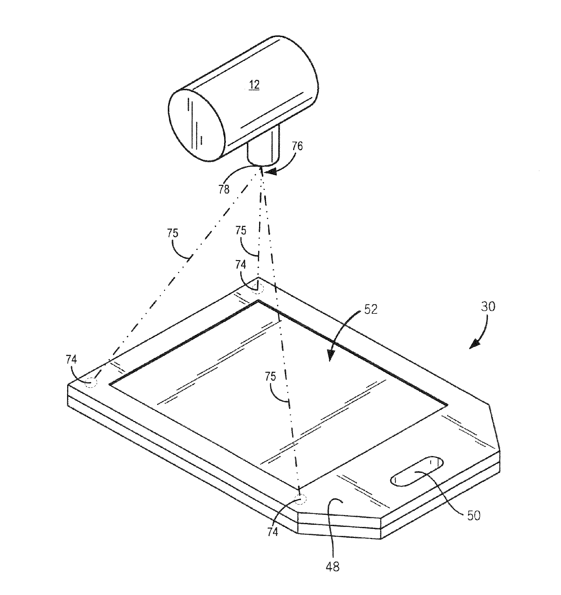
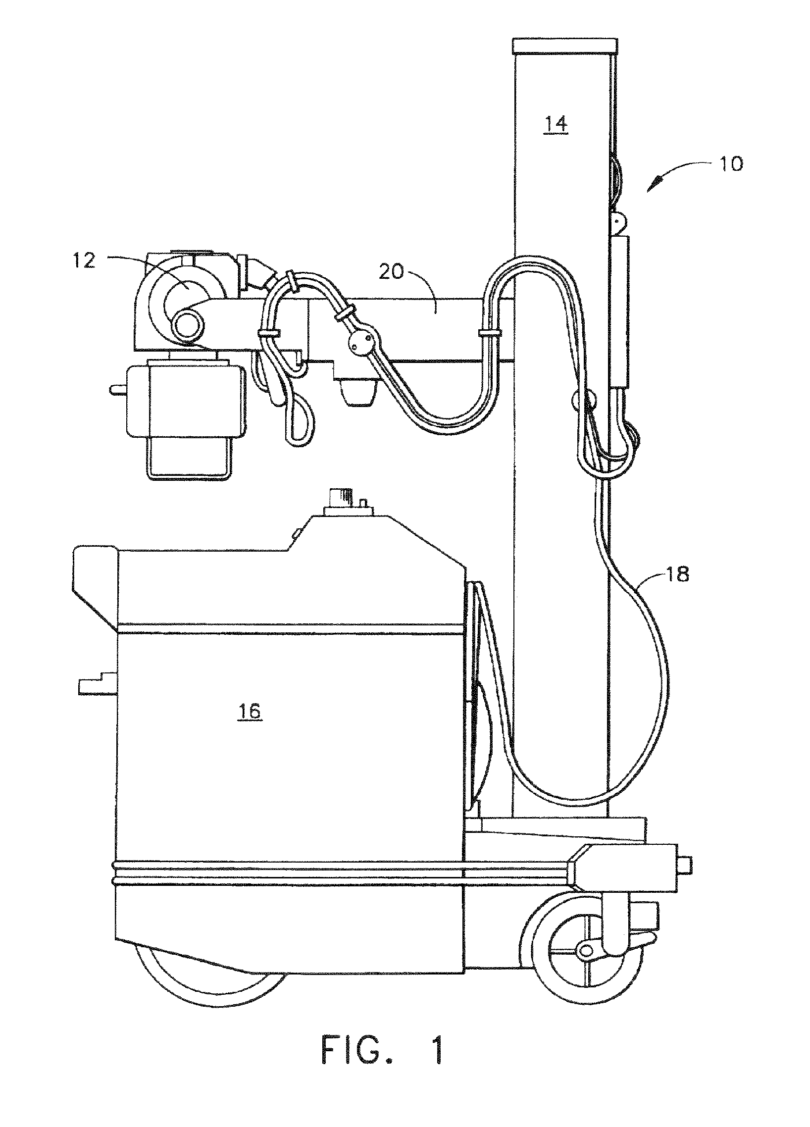
[0025] Referring now to FIG. 1, an exemplary mobile x-ray imaging system 10 applicable with a portable x-ray detector incorporating the present invention is shown. An x-ray source 12 is mounted or otherwise secured to an end of horizontal arm 20. Arm 20 allows the x-ray source 12 to be variably positioned above a subject in such a manner so as to optimize irradiation ...


PUM


Abstract

A method and system of aligning an x-ray detector and x-ray tube for data acquisition are presented. The x-ray detector and x-ray tube are equipped with transmitters and receivers designed to provide feedback relating to the orientation, spacing, and general position thereof. In this regard, a user can effectively and efficiently position the x-ray tube and x-ray detector relative to one another for data acquisition.

Description

BACKGROUND OF THE INVENTION [0001] The present invention relates generally to x-ray systems and, more particularly, to a method and system of aligning an x-ray detector such that the x-ray detector is perpendicular to and properly spaced from an x-ray tube during data acquisition. [0002] X-ray imaging is a non-invasive technique to capture images of medical patients for clinical diagnosis as well as inspect the contents of sealed containers, such as luggage, packages, and other parcels. To capture these images, an x-ray source irradiates a scan subject with a fan beam of x-rays. The x-rays are then attenuated as they pass through the scan subject. The degree of attenuation varies across the scan subject as a result of variances in the internal composition of the subject. The attenuated energy impinges upon an x-ray detector designed to convert the attenuating energy to a form usable in image reconstruction. A control system reads out electrical charge stored in the x-ray detector an...

Claims


Application Information

Patent Timeline
Patent Type & Authority Applications(United States)
IPC IPC(8): A61B6/08
CPCA61B6/08A61B6/4233A61B6/4405A61B6/547A61B6/587
Inventor ERTEL, JASON R.LAMBERTY, JOHN R.
Owner GENERAL ELECTRIC CO
Why Eureka
Try Eureka