Fuel cell stack

a fuel cell and stack technology, applied in the field of fuel cell stacks, can solve the problems of low power generation performance of end-use power generation cells, inability to smoothly discharge water produced in power generation, easy water condensation, etc., and achieve the effect of maintaining the desired power generation performance and simple and economical structur

Active Publication Date: 2006-05-25
HONDA MOTOR CO LTD
View PDF7 Cites 56 Cited by
  • Summary
  • Abstract
  • Description
  • Claims
  • Application Information

AI Technical Summary

Benefits of technology

[0011] A main object of the present invention is to provide a fuel cell stack having simple and economical structure in which it is possible to maintain the desired power generation performance.
[0014] Preferably, the dummy separator selectively blocks the fluid flow between the fluid flow field and the fluid passage. Therefore, the same separator can be used economically for controlling the supply of the reactant gas and the coolant easily.
[0015] Further, preferably, a heat insulating space is formed in the dummy cell or between the dummy cells. Therefore, the dummy cells function as heat insulating layers. It is possible to effectively prevent the delay in raising the temperature of the end power generation cell, and prevent the voltage drop in the end power generation cell at the time of starting operation of the fuel cell stack at a low temperature.
[0017] According to the present invention, no electrolyte is used in the dummy cell. Therefore, no water is produced in the power generation. The dummy cell functions as the heat insulating layer. Accordingly, it is possible to effectively prevent the delay in raising the temperature of the end power generation cell, and prevent the voltage drop in the end power generation cell at the time of starting operation of the fuel cell stack at a low temperature.
[0018] Further, the dummy separator having substantially the same structure as the structure of the separator of the power generation cell is used in the dummy cell. Therefore, common components can be used in both of the power generation cell and the dummy cell. In comparison with the case in which dedicated heat insulating plates or the like are used, the fuel cell stack can be produced economically as a whole.

Problems solved by technology

Therefore, due to the decrease in the temperature, in the end power generation cells, in comparison with power generation cells in the central position of the fuel cell stack, water condensation occurs easily, and the water produced in the power generation cannot be discharged smoothly.
Consequently, the power generation performance of the end power generation cells is low.
The total number of components of the fuel cell stack is increased significantly, and the fuel cell stack cannot be assembled easily.
Thus, the fuel cell stack cannot be produced economically.

Method used


Image

  • Fuel cell stack
  • Fuel cell stack
  • Fuel cell stack

Examples


Embodiment Construction

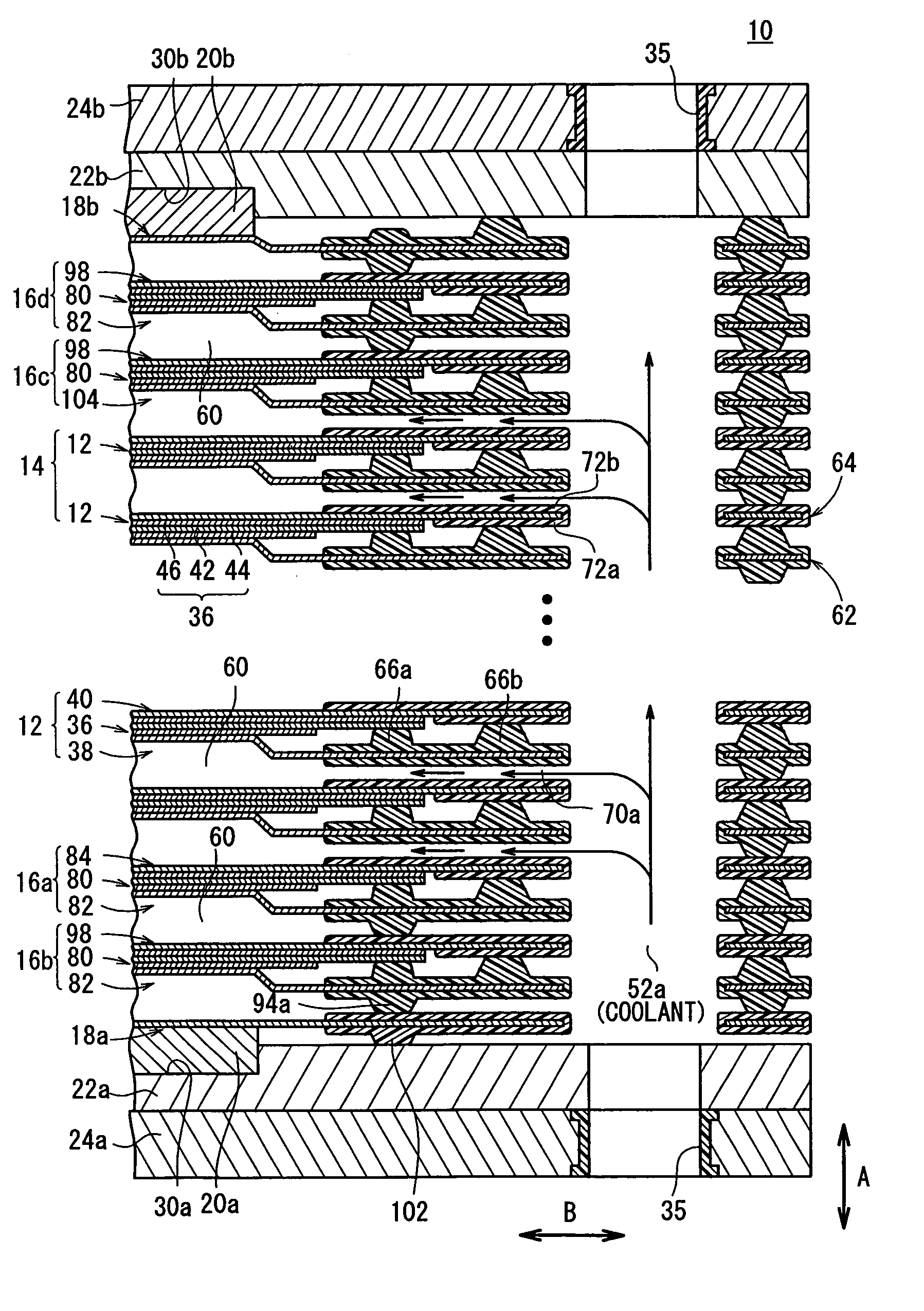
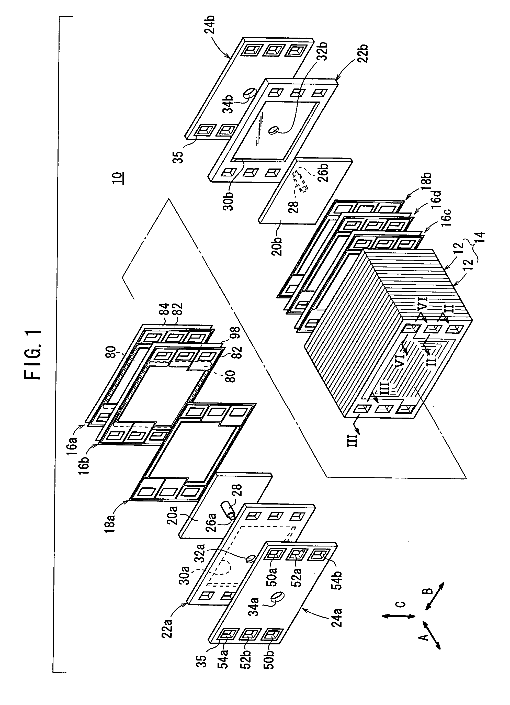
[0029]FIG. 1 is a partial exploded perspective view showing a fuel cell stack 10 according to an embodiment of the present invention. FIG. 2 is a cross sectional view showing the fuel cell stack 10, taken along a line II-II in FIG. 1. FIG. 3 is a cross sectional view showing the fuel cell stack 10, taken along a line III-III in FIG. 1. FIG. 4 is a cross sectional view showing the fuel cell stack 10, taken along a line IV-IV in FIG. 1.

[0030] The fuel cell stack 10 includes a stack body 14 formed by stacking a plurality of power generation cells 12 in a stacking direction indicated by the arrow A. At one end of the stack body 14 in the stacking direction indicated by the arrow A, a first dummy cell 16a is provided. A second dummy cell 16b is provided outside the first dummy cell 16a. Further, an end separator 18a is provided outside the second dummy cell 16b. At the other end of the stack body 14 in the stacking direction, a third dummy cell 16c is provided. A fourth dummy cell 16d i...


PUM

PropertyMeasurementUnit
electrically conductiveaaaaaaaaaa
structureaaaaaaaaaa
heat insulatingaaaaaaaaaa

Abstract

A fuel cell stack includes a stack body formed by stacking a plurality of power generation cells in a stacking direction. At one end of the stack body, first and second dummy cells are provided. At the other of the stack body, third and fourth dummy cells are provided. Each of the first to fourth dummy cells includes a first metal separator and a second metal separator. The first metal separator and a first metal separator of the power generation cell have substantially the same shape. The second metal separator and a second metal separator of the power generation cell have substantially the same shape.

Description

BACKGROUND OF THE INVENTION [0001] 1. Field of the Invention [0002] The present invention relates to a fuel cell stack comprising a stack body formed by stacking a plurality of power generation cells in a stacking direction. Each of the power generation cells includes an electrolyte electrode assembly and separators sandwiching the electrolyte electrode assembly. The electrolyte electrode assembly includes a pair of electrodes, and an electrolyte interposed between the electrodes. Each of the separators has a fluid flow field for allowing at least one of a reactant gas and a coolant to flow in a direction along a power generation surface. A fluid passage connected to the fluid flow field extends through the separators in the stacking direction. Terminal plates, insulating plates, and end plates are provided at opposite ends of the stack body. [0003] 2. Description of the Related Art [0004] In general, a polymer electrolyte fuel cell employs a membrane electrode assembly (electrolyte...

Claims


Application Information

Patent Timeline
Patent Type & Authority Applications(United States)
IPC IPC(8): H01M8/04H01M8/24H01M2/08
CPCH01M8/0258H01M8/0271H01M8/04007H01M8/04089H01M8/04268H01M8/241Y02E60/50H01M8/2483H01M8/0267H01M8/2457H01M8/0263H01M8/0276
Inventor NISHIYAMA, TADASHIINAI, SHIGERUKATO, HIDEOKONDO, JUNJINBA, RYO
Owner HONDA MOTOR CO LTD
Why Eureka
Try Eureka