

Text edition device and program
a text editing and program technology, applied in the field of text editing devices, can solve the problems of deteriorating the efficiency of text editing, inconvenient user, undesirable automatic enlargement of the frame once specified, etc., and achieve the effect of easy switching of operation modes and high workability
- Summary
- Abstract
- Description
- Claims
- Application Information
AI Technical Summary
Benefits of technology
Problems solved by technology
Method used
Image

Examples
embodiment 1
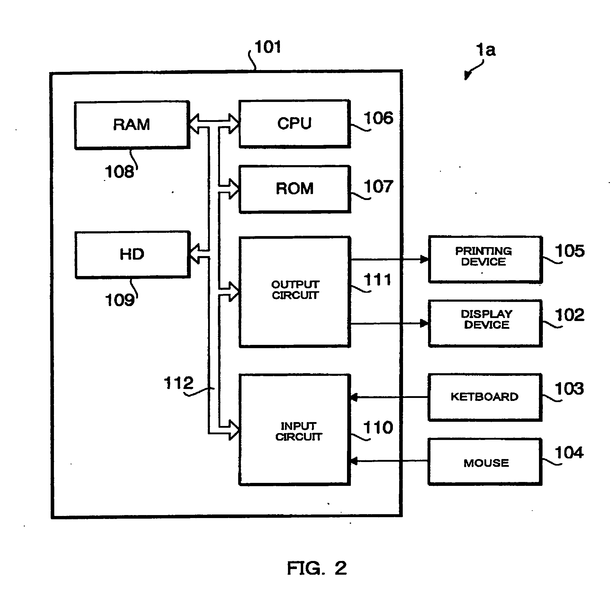
[0044]FIG. 2 is a block diagram showing the hardware configuration of a text editing device 1a in accordance with a first embodiment of the present invention.
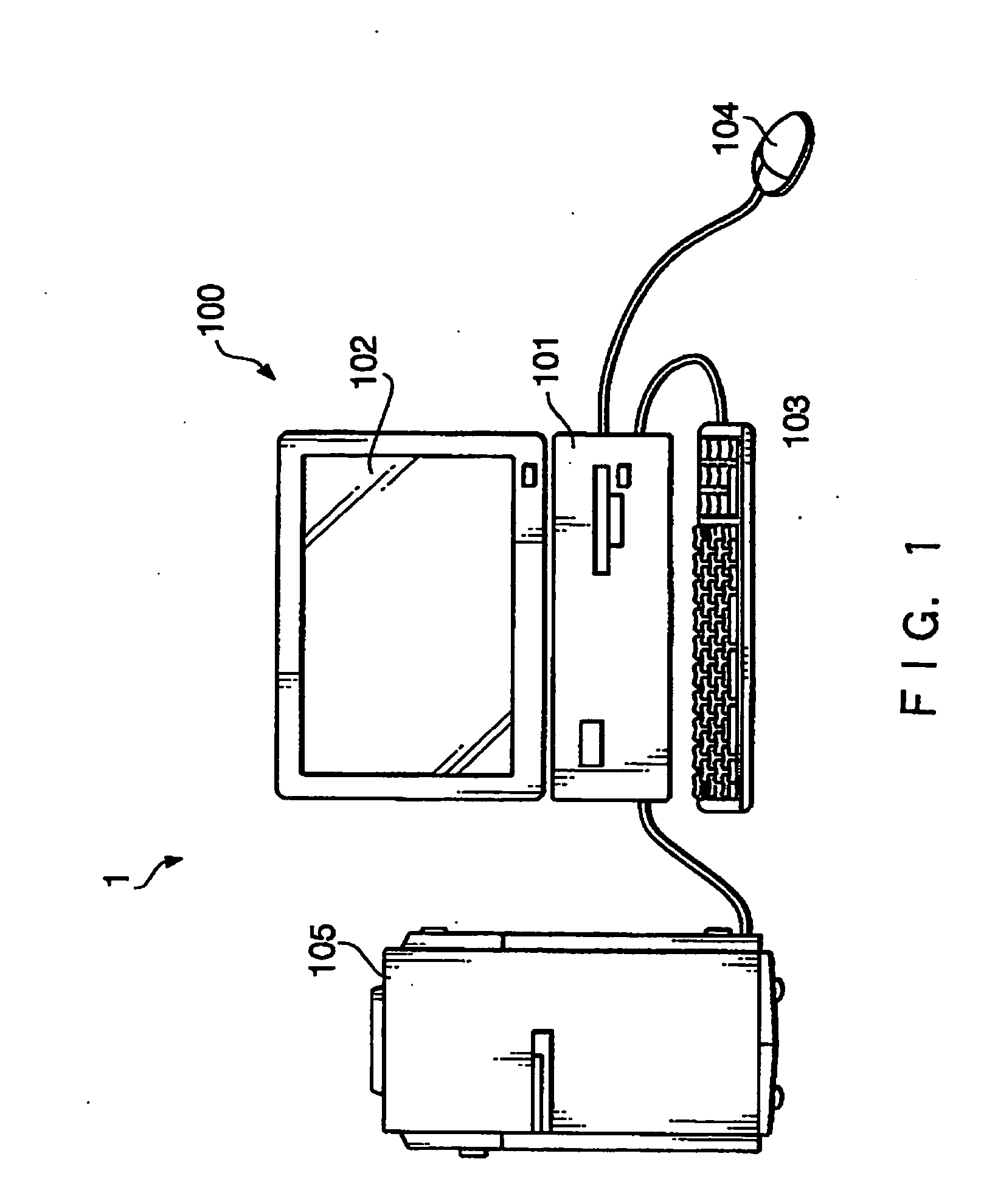
[0045] As shown in FIG. 2, inside the main body 101 of the personal computer 100 of the first embodiment, a CPU (Central Processing Unit) 106, a ROM (Read Only Memory) 107, a RAM (Random Access Memory) 108, an HD (Hard Disk) 109, an input circuit 110 and an output circuit 111 are connected together by a bus 112. To the main body 101, the printing device 105 and the display device 102 are connected via the output circuit 111, while the keyboard 103 and the mouse 104 are connected via the input circuit 110.
[0046] The ROM 107 is a read-only storage device storing various programs to be used for controlling the operation of the text editing device 1a. The hard disk (HD) 109 is a readable and writable storage device storing a variety of software including a program for letting the computer function as the text editing device 1a (T...
embodiment 2
[0089] In the following, a second embodiment in accordance with the present invention will be described referring to figures.
[0090]FIG. 11 is a block diagram showing an example of hardware configuration installed in a text editing device 1b in accordance with the second embodiment of the present invention. The text editing device 1b includes a CPU (Central Processing Unit) 211, a ROM (Read Only Memory) 212, a RAM (Random Access Memory) 213, a hard disk (HD) 214 and an interface (I / F) 215 which are connected together by a bus 231.
[0091] A display device 102, operating devices (keyboard 103, mouse 104) and a printing device 105 are connected to the CPU 211 via the interface (I / F) 215. As the printing device 105, various types of printing devices, such as a tape printer for printing character strings on tape-like print media, a printer for printing on plain paper (A4 size, B4 size, postcard size, etc.) as print media, a stamp producing device for producing a stamp or seal, etc. can b...
example 1
INITIAL SETTING EXAMPLE 1
[0136] When the print medium on which the character string stored in the text storage module 221 will be printed is a tape-like print medium and the size of a print area of the medium in its longitudinal direction is preset, the operation mode setting module 227 initially sets the “set operation mode” to the “frame configuration fixed operation mode”, and the “frame configuration fixed operation mode” is stored in the frame configuration storage module 223, by which the user starting up the text editing device 1b can immediately start text editing work while recognizing the fixed frame configuration as the preset print area of the tape-like print medium, without the need of setting the operation mode.
PUM
 Abstract
Description
Claims
Application Information