Heat exchanger

a technology of heat exchanger and tank body, which is applied in the direction of indirect heat exchanger, lighting and heating apparatus, stationary conduit assemblies, etc., can solve the problems of difficult to maintain the capacity of the inner space of the tank, easy to cause brazing defects at the brazing junction, and complicated tank construction, etc., to achieve stable brazing performance and reduce the brazing parts of the tank

Inactive Publication Date: 2006-06-01
DENSO CORP
View PDF6 Cites 8 Cited by
  • Summary
  • Abstract
  • Description
  • Claims
  • Application Information

AI Technical Summary

Benefits of technology

[0020] Thus, the brazing parts of the tank can be reduced because the tank is constructed of

Problems solved by technology

However, the construction of the tank is complicated due to the overlapped junction parts of the end plate member and the tank plate member.
In this case, it is difficult to maintain the capacity of the inner space of the tank, in which refrigerant flows.
If an end surface of the one plate member is arranged to contact an inner surface of the other plate member at the brazing junction therebetween in order to maintain the capacity of the inner sp

Method used


Image

  • Heat exchanger
  • Heat exchanger
  • Heat exchanger

Examples


first embodiment

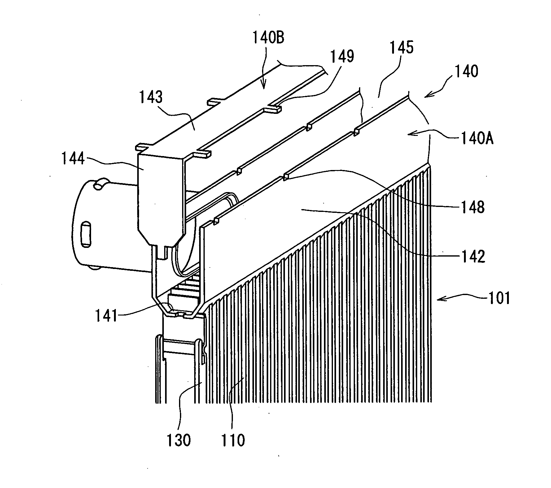
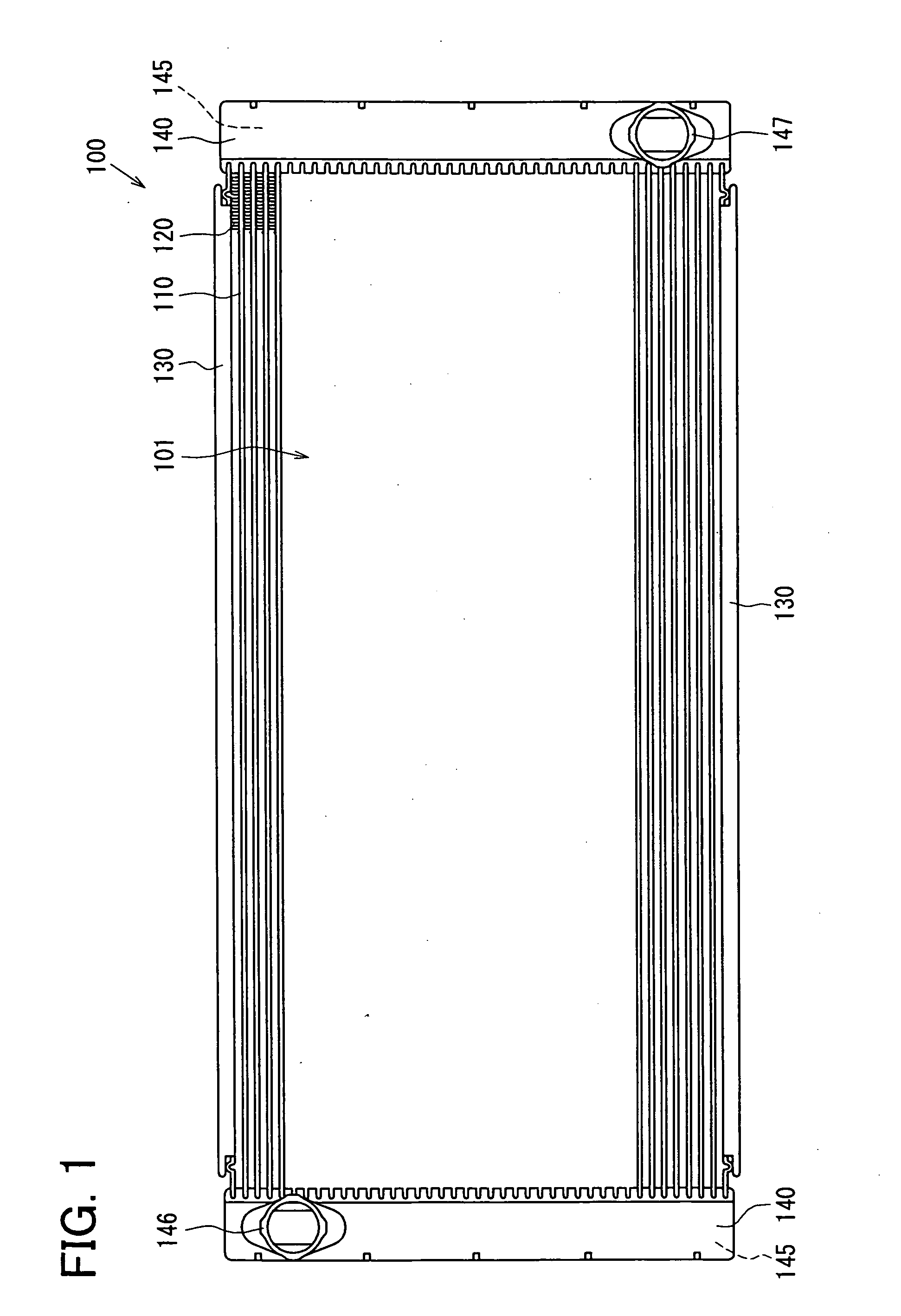
[0052] A heat exchanger 100 (e.g., radiator) according to a first embodiment of the present invention will be described with reference to FIGS. 1-7B. The radiator 100 can be suitably used to cool cooling water of an engine. Referring to FIG. 1, the radiator 100 has multiple tubes 110 (partially shown), multiple fins 120 (partially shown), two side plates 130, two tanks 140 and the like, which are made of, for example, aluminum (or aluminum alloy) and integrated by brazing or the like.

[0053] As shown in FIG. 1, the tubes 110 of the radiator 100 (e.g., cross flow type) can be arranged in a horizontal direction. The radiator 100 mainly includes a core unit 101 and the two tanks 140.

[0054] The core unit 101 (heat radiating unit), in which cooling water is cooled, includes the flat-shaped tubes 110, the corrugated fins 120 and the side plates 130. The tubes 110 and the fins 120 are alternately stacked (laminated). That is, each of the tubes 110 is arranged between the adjacent fins 120...

second embodiment

[0094] A second embodiment will be described with reference to FIGS. 8A-9. In this case, the second plate member 140B is further provided with ribs (e.g., recesses) 143a and 143b, as compared with the above-described first embodiment.

[0095] As shown in FIGS. 8A-8C, the opposite wall portion 143 of the second plate member 140B is provided with the recess 143a extending in the longitudinal direction of the opposite wall portion 143. The cap portion 144 is provided with the recess 143b extending in the erection direction of the cap portion 144. The recess 143a, 143b has a concave shape (when being viewed from outer side of tank 140) to protrude into the inner space 145 of the tank 140.

[0096] According to the second embodiment, the stiffness of the second plate member 140B can be increased by the ribs (recesses) 143a and 143b. Therefore, the deformation of the second plate member 140B when being mounted at the first plate member 140A to construct the tank 140 can be restricted. Accord...

third embodiment

[0102] A third embodiment of the present invention will be described with reference to FIGS. 10 and 11. In this case, the junction of the side wall portions 142 and the cap portion 144 is changed as a first modification of the first embodiment.

[0103] As shown in FIG. 10, each of the side wall portions 142 of the first plate member 140A is provided with two junction grooves 142a (being concave portion when being viewed from inner side of tank 140), which are respectively arranged at the two longitudinal-direction ends of the side wall portion 142 and respectively disposed at the positions corresponding to the mounting positions of the cap portions 144. The junction groove 142a convexes toward the outer side of the tank 140.

[0104] In this case, the width (dimension perpendicular to longitudinal directions of second plate member 140B and tube 110) of the cap portion 144 is set larger than that of the opposite wall portion 143. The width of the opposite wall portion 143 is substantial...


PUM


Abstract

A heat exchanger has a tank communicated with tubes at longitudinal-direction ends of the tubes. A first plate member of the tank has a core plate portion connected with the tubes and two side wall portions facing each other, which are constructed of a metal plate material. The second plate member of the tank has an opposite wall portion facing the core plate portion and two cap portions facing each other, which are constructed of a metal plate material. The core plate portion has a protrusion-shaped cross section in the longitudinal direction of the tubes. The first plate member and the second plate member are integrated by brazing. An inner surface of one of the plate members contacts an end surface of other of the plate members, and a fillet is formed between an extension portion of the one plate member and a shear droop of the other plate member.

Description

CROSS REFERENCE TO RELATED APPLICATION [0001] This application is based on Japanese Patent Applications No. 2004-344809 filed on Nov. 29, 2004 and No. 2004-363624 filed on Dec. 15, 2004, the disclosure of which is incorporated herein by reference. FIELD OF THE INVENTION [0002] The present invention relates to a heat exchanger having a tank which is constructed of multiple metal plate members. BACKGROUND OF THE INVENTION [0003] Generally, referring to JP-2002-213895A, a tank of a heat exchanger is constructed of four metal plate members which are integrally joined to each other by brazing. Among the four plate members, the end plate member (core plate portion) and the tank plate member (which constructs side wall portions and opposite wall portion facing core plate portion) are respectively provided with plane-shaped junction parts, which are overlapped to be integrated by brazing. [0004] However, the construction of the tank is complicated due to the overlapped junction parts of the...

Claims


Application Information

Patent Timeline
IPC IPC(8): F28F9/02
CPCF28D2021/0094F28F9/0224F28F2275/04
Inventor NINAGAWA, TOSHIHIDEOZAKI, TATSUOSAKO, YUUJI
Owner DENSO CORP
Why Eureka
Try Eureka