Electric component and its manufacturing material

a technology of manufacturing material and electric component, applied in the direction of magnets, cores/yokes, magnetic bodies, etc., can solve the problems of unnecessary increase of manufacturing cost and unnecessary waste of materials

Inactive Publication Date: 2006-06-01
JUNG FONG ELECTRONICS
View PDF6 Cites 5 Cited by
  • Summary
  • Abstract
  • Description
  • Claims
  • Application Information

AI Technical Summary

Benefits of technology

[0003] Therefore, it is a primary objective of the present invention to solve the foregoing problems and avoid the existing deficiencies by providing a novel method for producing a U-shape silicon steel plate, and each electric component group comprises a first and a second symmetric silicon steel plates, and the first and second silicon steel plates individually have a long end section, a short end section, and a connecting section for connecting the long and short end sections, and the first and second silicon steel plates are intersected on a carrier tape to define a structure arranged in the order of the long end section, the short end section, the long end section and the short end section as to reduce the material waste of the carrier tape and save unnecessary material costs.

Problems solved by technology

As to the manufacture, if the UU-shape silicon plate is used to produce electric components, then manufacturers have to make other arrangements for the material planning of the I-shape silicon steel plate 1c; if the UI-shape silicon plate is used to produce electric components, then manufacturers have to handle the problem of preparing additional quantity of material to cover a great deal of the remained U-shape silicon steel plate 1a, 1b. Manufacturers cannot afford such unnecessary waste of materials, since scraping the remained material causes an unnecessary increase of the manufacturing cost.

Method used


Image

  • Electric component and its manufacturing material
  • Electric component and its manufacturing material
  • Electric component and its manufacturing material

Examples


Embodiment Construction

[0007] The above and other objects, features and advantages of the present invention will become apparent from the following detailed description taken with the accompanying drawing.

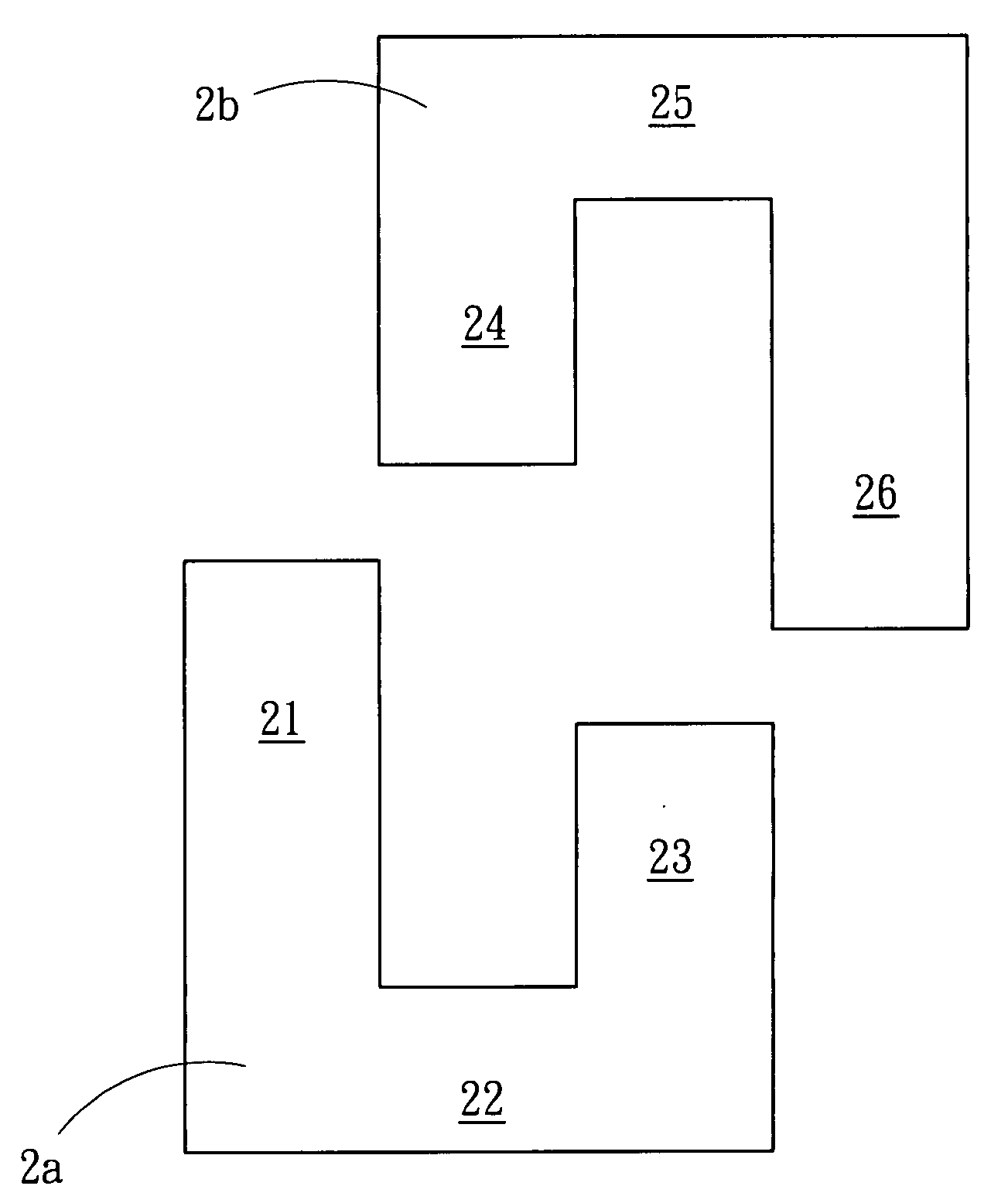
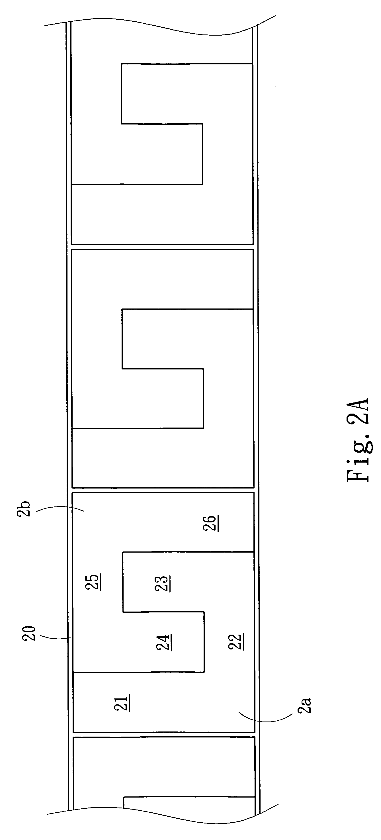
[0008] Please refer to FIG. 2A for the schematic view of a carrier tape containing electric components according to the present invention. In the figure, the electric component and its manufacturing material in accordance with the present invention produce a plurality of electric component groups on a carrier tape 20, wherein each electric component group is made of a first and a second symmetric silicon plates 2a and 2b, and the first and second silicon steel plates 2a and 2b individually have a long end section 21, 26, a short end section 23, 24 and a connecting section 22, 25 for connecting the long and short sections 21, 23, 24, 26 and the length of the long end section 21, 26 is equal to the sum of the length of the short end section 23, 24 and the length of the connecting end 22, 25 (such that the...


PUM

PropertyMeasurementUnit
lengthaaaaaaaaaa
vertical heightaaaaaaaaaa
lengthsaaaaaaaaaa

Abstract

The present invention discloses an electric component and its manufacturing material, of which a plurality of electric component groups is produced on a carrier tape and each electric component group is made of a first and a second symmetric silicon plates, and the first and second silicon steel plates individually have a long end section, a short end section and a connecting section for connecting the long and short sections, and the first and second silicon steel plates are interested on the carrier tape to define a structure arranged in the order of the long end section, the short end section, the short end section and the long end section as to reduce the waste of material on the carrier tape and save unnecessary material costs.

Description

FIELD OF THE INVENTION [0001] The present invention relates to an electric component and its manufacturing material, more particularly to an electric component to be applied to a U-shape silicon steel plate, such that a U-shape silicon plate group is produced on a carrier tape to reduce a waste of materials and lower unnecessary material costs effectively. BACKGROUND OF THE INVENTION [0002] In general, an electric component such as an inductor, a transformer, or a choke coil usually adopts a connecting type silicon steel plate wrapped by a coil for its electric connection to produce an electromagnetic field. Various different combinations of iron cores are designed according to the inductance and the overall volume of the structure and four common ones include the EE-shape, EI-shape, UU-shape and UI-shape. For manufacturing, the I-shape silicon steel plate is the simplest one, and the E-shape and U-shape silicon steel plates generally cause problems to the production due to their sp...

Claims


Application Information

Patent Timeline
Patent Type & Authority Applications(United States)
IPC IPC(8): H01F27/28
CPCH01F41/0233
Inventor LEE, MU-TU
Owner JUNG FONG ELECTRONICS
Why Eureka
Try Eureka