Method and apparatus for dimming hot cathode fluorescent lamp

a fluorescent lamp and hot cathode technology, applied in mechanical equipment, electric ignition installation, machines/engines, etc., can solve the problems of inability to adjust the brightness of traditional fluorescent lamps, huge inconvenience for users, etc., to prolong the life expectancy of piezoelectric transformers, high operating temperature, and without adversely affecting the life expectancy of lamps

Inactive Publication Date: 2008-02-28
ZIPPY TECH
View PDF1 Cites 0 Cited by
  • Summary
  • Abstract
  • Description
  • Claims
  • Application Information

AI Technical Summary

Benefits of technology

[0005]The primary objective of the present invention is to overcome the foregoing shortcomings and avoid the existing deficiencies by providing a method for dimming a hot cathode fluorescent lamp that employs frequency conversion and pulse width modulation to change the outputted voltage and current of a piezoelectric transformer, so as to achieve the purpose of adjusting the brightness of the hot cathode fluorescent lamp.
[0007]Another objective of the present invention is to provide a power supply control apparatus for adjusting the outputted voltage and current of a piezoelectric transformer without adversely affecting the life expectancy of the lamp.
[0008]The invention further uses a PWM control unit to integrate pulse width modulation control with dynamic frequency conversion control and also uses the frequency conversion to adjust the voltage gain of a piezoelectric transformer without changing the amplitude of vibration of the resonant frequency, so that the duty ratio can achieve the purpose of changing the outputted voltage and current of the piezoelectric transformer. The method in accordance with the present invention will not frequently charge or stop charging the piezoelectric transformer. Unlike the traditional burst mode or control method of pulse width modulation, the apparatus of the present invention further helps extending the life expectancy of the piezoelectric transformer by substituting the starter and voltage regulator of the hot cathode fluorescent lamp of present technologies, so that the hot cathode fluorescent lamp no longer needs a ballast that results in a high operating temperature. The present invention not just extends the life expectancy of the lamp and reduces the number of components, but also provides a quick start for the lamp.

Problems solved by technology

Although the fluorescent lamp can achieve the illumination purpose, the brightness of the traditional fluorescent lamp cannot be adjusted by users based on the environment of the installed lamp, and the brightness of the lamp depends on the length of the lamp.
If users want to adjust the required brightness of the illumination for the environment, then it is necessary to change a lamp of a different length, and thus causing tremendous inconvenience to users.

Method used


Image

  • Method and apparatus for dimming hot cathode fluorescent lamp
  • Method and apparatus for dimming hot cathode fluorescent lamp
  • Method and apparatus for dimming hot cathode fluorescent lamp

Examples


Embodiment Construction

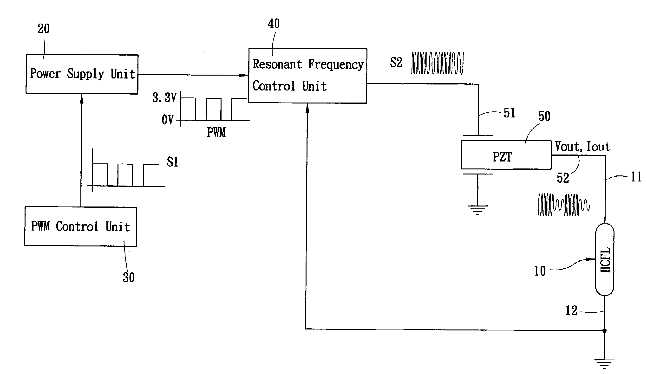
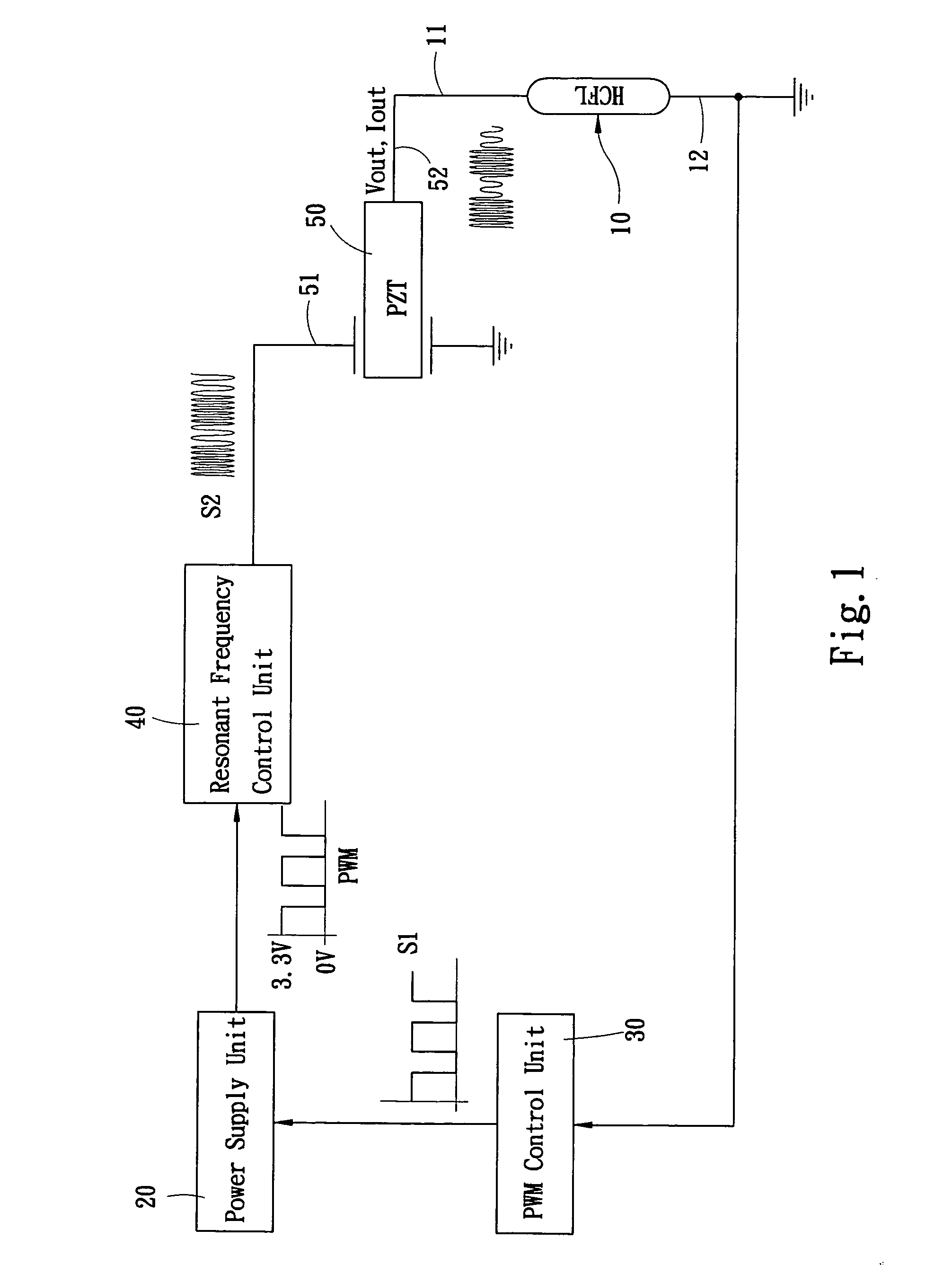
[0018]Referring to FIG. 1 for a circuit diagram of a first preferred embodiment of the present invention, the circuit is applied to an apparatus for dimming a hot cathode fluorescent lamp 10 that comprises:

[0019]a power supply unit 20, for providing a direct current power supply (depending on the specification of the hot cathode fluorescent lamp 10 and generally is a direct current power supply of zero volt to several volts) required for driving the hot cathode fluorescent lamp 10;

[0020]a PWM control unit 30, for outputting a pulse wave signal S1 by the pulse width modulation technology and controlling a pulse width modulation control signal by the pulse wave signal S1 in order to control the power supply unit 20 to output Ton and Toff with duty cycles. In other words, the pulse wave signal S1 is used to change the duty ratio of a direct current (DC) power supply of 0V outputted by the power supply unit 20 and a full-scale output (such as 3.3V), and their output waveforms are shown ...


PUM


Abstract

The present invention discloses a method and an apparatus for dimming a hot cathode fluorescent lamp (HCFL) that combines frequency conversion and pulse width modulation (PWM) to change the outputted voltage and current of a piezoelectric transformer, so as to achieve the purpose of adjusting the brightness of a cathode fluorescent lamp. The invention can substitute a starter and a voltage regulator of a hot cathode fluorescent lamp without the need of installing a ballast that produces high heat during its operation easily, and extend the life expectancy of the fluorescent lamp, reduces the number components of the fluorescent lamp, and provides a quick start of the lamp.

Description

FIELD OF THE INVENTION[0001]The present invention relates to a method and an apparatus for dimming a hot cathode fluorescent lamp, and more particularly to a method and an apparatus for changing an output voltage and power supply to adjust the brightness of a hot cathode fluorescent lamp.BACKGROUND OF THE INVENTION[0002]In the installation configuration of a common fluorescent lamp available in the market, electrodes on both ends of the fluorescent lamp are electrically connected to a starter, a ballast and a switch. The fluorescent lamp is simply considered as a sealed gas discharge tube. The gas in the tube is mainly argon gas (and including neon or krypton) with an air pressure approximately equal to 0.3% of an atmosphere, and the tube also contains a small amount of mercury approximately equal to one-thousandth of the gas.[0003]By the accelerated electrons of sufficient electric field in the fluorescent lamp, the gas in the lamp is ionized to excite the gas (the mercury atoms ab...

Claims


Application Information

Patent Timeline
Patent Type & Authority Applications(United States)
IPC IPC(8): F02P3/12
CPCH05B41/3925H05B41/2828
Inventor CHOU, CHIN-WENCHENG, YING-NAN
Owner ZIPPY TECH
Why Eureka
Try Eureka