
Fan assembly for a power supply

Active Publication Date: 2006-06-22
ZIPPY TECH
View PDF13 Cites 6 Cited by
  • Summary
  • Abstract
  • Description
  • Claims
  • Application Information

AI Technical Summary

Benefits of technology

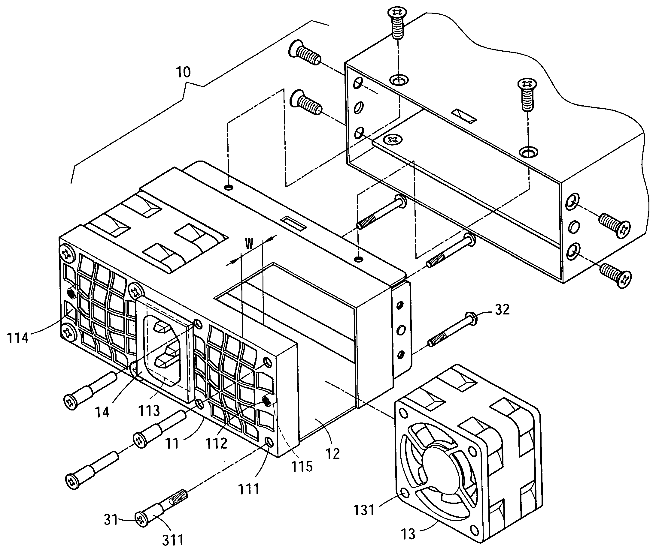
[0004] Therefore, the primary objective of the present invention is to solve the foregoing problems and avoid the existing deficiencies by providing a fan assembly to improve the traditional installation of a fan onto a power supply that leaves not enough space for designing the connecting holes as required by the existing installation specification, and mounts the fan into a power supply at a specific position by a fixing member, and uses the fixing member to keep the fan at a specific interval from the end surface of the power supply without being in direct contact with the fan. Therefore, the interval between the end surface and the power supply provides enough space for the design of the ventilation holes for the airflow and the connecting holes as required by the specification of installing the power supply. Such arrangement allows the end surface of the power supply to accommodate various electronic devices of different specifications and provides more spaces for other designs, and thus the power supply in accordance with the present invention becomes popular.

Problems solved by technology

However, when the power supply is switching, a great deal of heat is produced due to a power loss.
However, one fan no longer can meet the requirement for dispersing so much heat produced by a high-power power supply.
These designs may ruin the existing external look of the power supply and limit the way of installing a power supply onto an electronic device appropriately.
From the figure, it is obvious that the design of the connecting holes is unable to meet the requirement for a universal connection at the existing installation position of the electronic device.
In other words, the computer power supply must be designed according to some other specification for its assembly and installation, and thus this type of power supply cannot fully meet the universal application and needs further improvements.

Method used


Image

  • Fan assembly for a power supply
  • Fan assembly for a power supply
  • Fan assembly for a power supply

Examples


Embodiment Construction

[0011] The above and other objects, features, and advantages of the present invention will become apparent from the following detailed description taken with the accompanying drawing.

[0012] Please refer to FIGS. 4 to 7 for the perspective view, the exploded view, the schematic view of the structure and the schematic view of the structure with an installed electronic device 20 according to the present invention. In the figures, the present invention comprises a fan assembly 13 of a power supply 10 and the power supply is installed in an electronic device 20, and the electronic device 20 has an installation position 21 for installing the power supply 10 onto the electronic device 20; wherein a fan 13 is installed on any end surface 11 of the power supply 10 for dispersing heat. The size and quantity of the fan 13 follow the existing specification for the corresponding power supply 10, and the embodiment of the present invention adopts the design of dual fans 13, and the end surface 1...


PUM


Abstract

The present invention discloses a fan assembly for a power supply and improves the traditional installation of a fan onto a power supply that leaves insufficient spaces for designing the connecting holes as required by the existing installation specification, and mounts the fan into a power supply at a specific position by a specific fixing member and uses the fixing member to keep the fan at a specific interval from the end surface of the power supply without being in direct contact with the power supply. Therefore, the interval from the end surface provides sufficient space for the design of the ventilation holes for the airflow and the connecting holes as required by the installation specification of the power supply.

Description

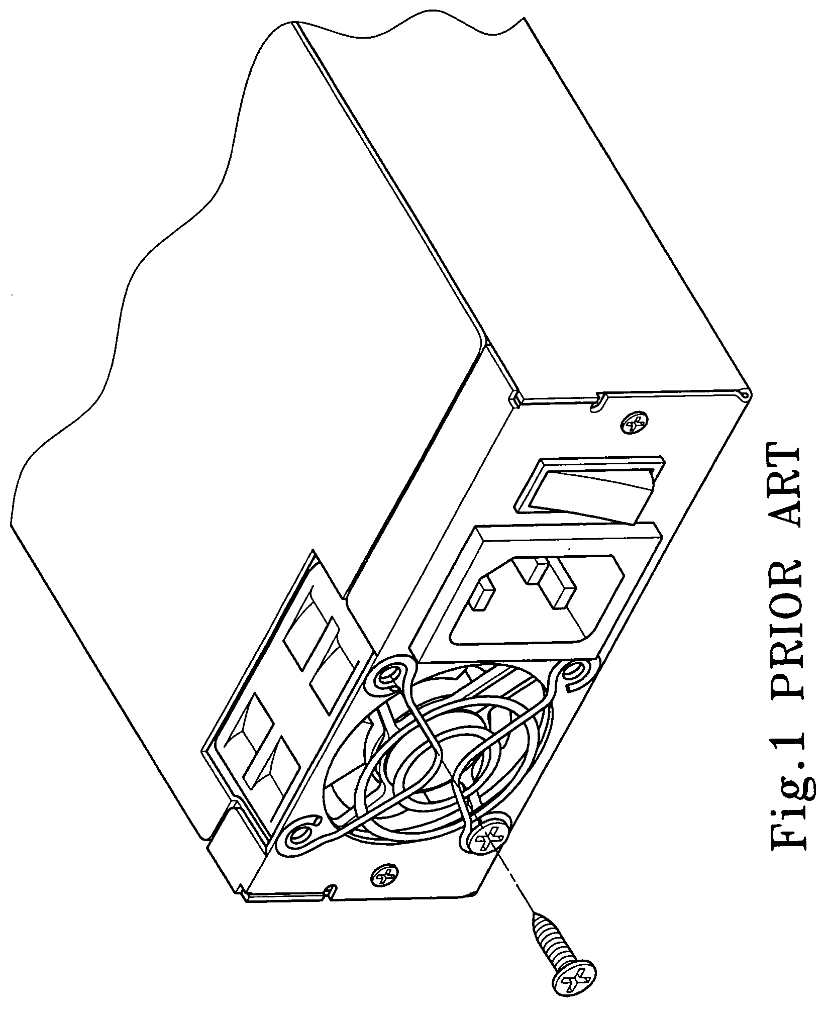
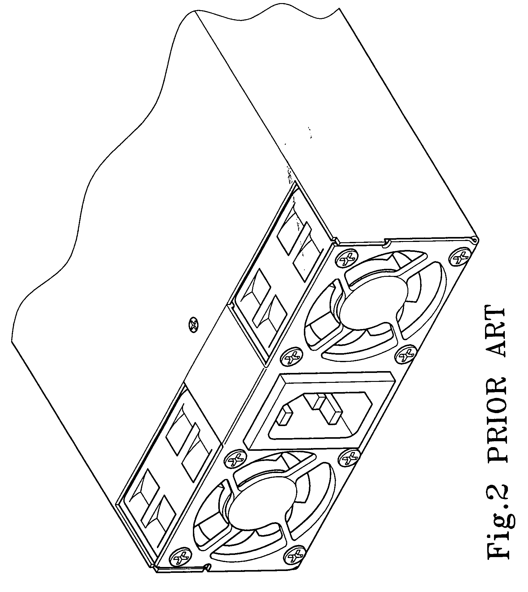
FIELD OF THE INVENTION [0001] The present invention relates to a fan assembly for a power supply, more particularly to a fan assembly mounted onto an end surface of a power supply that remains enough space for designing the connecting holes required by the specification of installing a power supply to an electronic device. BACKGROUND OF THE INVENTION [0002] A power supply could be considered as the most important part of an electronic device that supplies electric power for the operation of the electronic device. However, when the power supply is switching, a great deal of heat is produced due to a power loss. Thus, a power supply usually comes with a fan for dispersing the heat as shown in FIG. 1. The fan of a power supply is usually installed at an end surface of the power supply, and a through hole is disposed at a connecting hole on the end surface corresponding to an end of the fan, and the connection is usually achieved by securing a screw into the through hole to mount the fa...

Claims


Application Information

Patent Timeline
IPC IPC(8): H05K7/20
CPCH05K7/20172
Inventor LEE, TZUNG-HAN
Owner ZIPPY TECH
Learn More