Method of loading tendons into the knee

a technology of tendons and knees, applied in the field of anterior cruciate ligament reconstruction, can solve the problems of disadvantageous fixation methods, staples and suture buttons, and provide sufficient fixation

Inactive Publication Date: 2006-06-01
ARTHREX
View PDF19 Cites 38 Cited by
  • Summary
  • Abstract
  • Description
  • Claims
  • Application Information

AI Technical Summary

Benefits of technology

[0015] The present invention overcomes the problems of the prior art and fulfills needs such as those noted above by providing a surgical method for loading tendon grafts into a joint and fixating the grafts using a transverse, intraosseous implant. The inventive technique advantageously uses narrow tibial and femoral tunnels, and eliminates the use of sutures, tapes, or extra-osseous metal fixation devices. The procedure also is indicated for revisions that would otherwise be jeopardized by secondary femoral tunnel creation. In addition, the technique can be implemented using a transverse implant that is advanced by impaction into the bone.
[0022] The cannulated implant is placed over the wire and driven into the femur. The implant preferably is formed with back-biting threads. Accordingly, the implant easily can be impact driven into the repair site, and yet can be removed if necessary by rotation. The cannulated implant passes over the strand and under the tendon, thus securing the graft in the femoral socket.

Problems solved by technology

Various problems exist with the known fixation methods.
Staples and suture buttons are disadvantageous because they often do not provide fixation sufficient to withstand the normal tensile loads.
Although interference screw attachment is more secure than using staples or suture buttons, it is sometimes neither possible nor desirable to provide such fixation, particularly in the femoral tunnel.
Although a bone-semitendinosus graft-bone construct may be prepared using a workstation as disclosed in U.S. Pat. No. 5,397,357, such a procedure is time consuming, and may be undesirable for other reasons.
The technique is disadvantageous, however, because the graft can become wrapped around the implant as it is rotated.
As a result, the large femoral tunnel undesirably allows the graft to slide laterally, or “wipe” back and forth, along the fixation implant.
Moreover, the diameter of the implant necessarily is limited by the size of the opening in the forked insertion tool.
As a further disadvantage, the technique also requires the extra steps of forming and wedging a bone plug into the femoral tunnel after insertion of the ligament.
Moreover, the technique does not accommodate a closed-loop graft construct, since the graft must have a free end in order to be inserted with the forked insertion tool.
Further, the technique may not be indicated in revision procedures.

Method used


Image

  • Method of loading tendons into the knee
  • Method of loading tendons into the knee
  • Method of loading tendons into the knee

Examples


Embodiment Construction

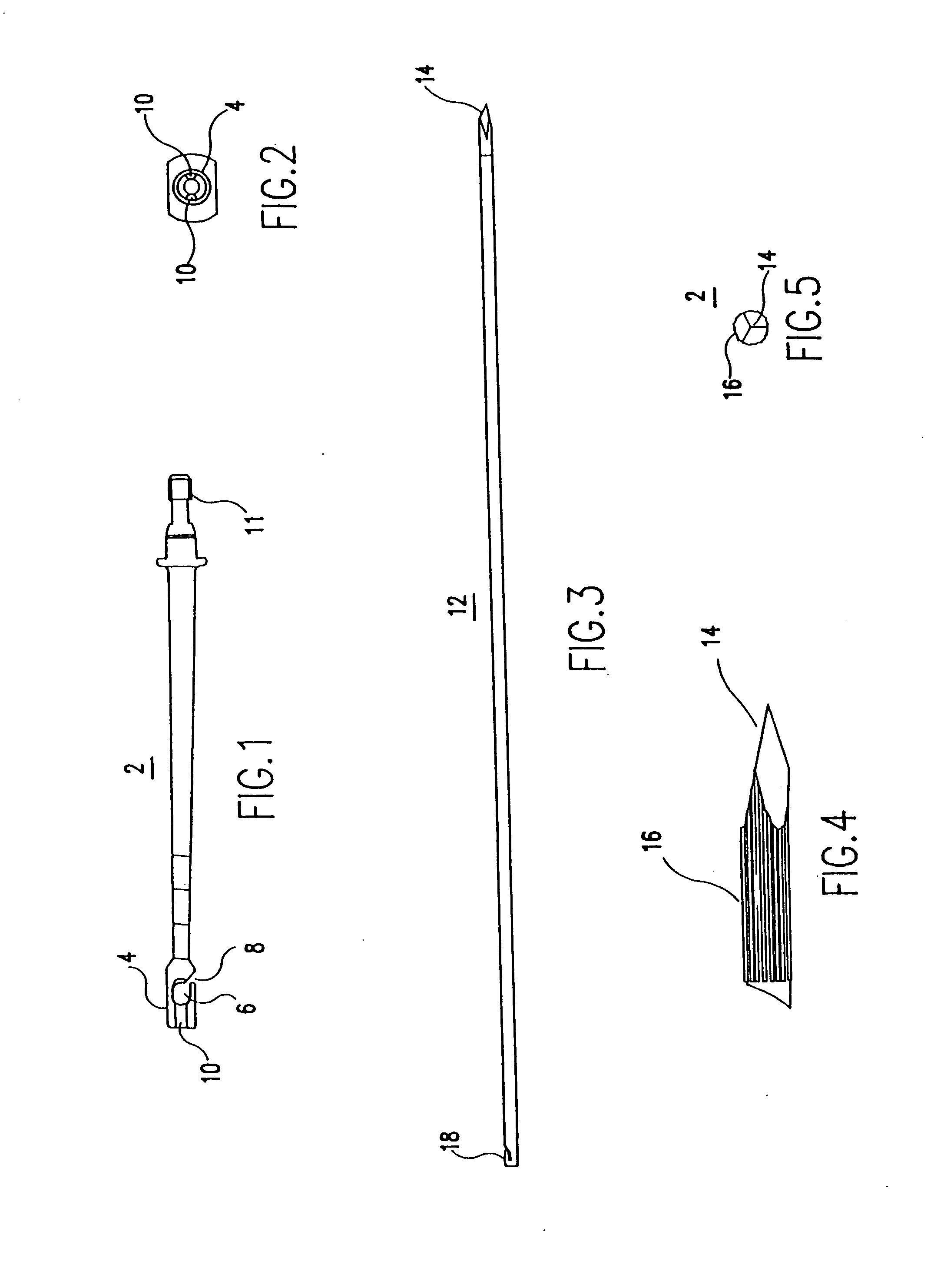
[0042] Referring initially to FIGS. 1 and 2, the present invention involves the use of a slim, longitudinal tunnel hook 2, which includes a shaft having a distal end and a proximal end. The distal end of tunnel hook 2 is provided with a hook 4, having a capture slot 6.

[0043] Various features of tunnel hook 2 are provided for ease of use in the inventive procedure of the present invention. The purpose of the following features will become more clear in light of the method described below. Angled opening 8 allows escape of a graft-passing wire from capture slot 6. Channels 10 on either side of hook 4 accommodate portions of the graft-passing wire as it forms a loop through a femoral tunnel. The proximal end of tunnel hook 2 features a mounting flange 11 for engagement with a drill guide.

[0044] Referring to FIGS. 3, 4, and 5, the invention also involves the use of a drill pin 12, which includes an elongated, narrow shaft having a pointed distal end and a proximal end. The distal end ...


PUM


Abstract

A surgical method for loading ligament grafts into a joint. A longitudinal socket formed in a bone is intersected by a transverse pin. A flexible strand is drawn with the pin through the bone. A looped portion of the strand is diverted so as to protrude out of the entrance to the longitudinal socket. The ends of the strand remaining accessible on either side of the bone. The ligament graft is captured within the strand loop protruding from the entrance to the socket. The strand is retracted into the socket, drawing the graft into the socket by pulling on the accessible ends of the flexible strand. The graft is fixed in the socket using a transverse implant.

Description

[0001] This application is a continuation of U.S. application Ser. No. 10 / 824,603, filed Apr. 15, 2004, now U.S. Pat. No. 6,974,477, which is a continuation of U.S. application Ser. No. 10 / 355,287, filed Jan. 31, 2003, now U.S. Pat. No. 6,733,529, which is a division of U.S. application Ser. No. 10 / 121,610, filed Apr. 15, 2002, now U.S. Pat. No. 6,537,319, which is a continuation of U.S. application Ser. No. 09 / 663,798, filed Sep. 18, 2000, now U.S. Pat. No. 6,371,124, which is a continuation of U.S. application Ser. No. 09 / 346,709, filed Jul. 2, 1999, now U.S. Pat. No. 6,132,433, which is a continuation of U.S. application Ser. No. 09 / 015,618, filed Jan. 29, 1998, now U.S. Pat. No. 5,918,604, which claims the benefit of U.S. Provisional Application Ser. No. 60 / 037,610, filed Feb. 12, 1997.BACKGROUND OF THE INVENTION [0002] 1. Field of the Invention [0003] The present invention relates to reconstruction of the anterior cruciate ligament (ACL), and, more specifically, to surgical gra...

Claims


Application Information

Patent Timeline
Patent Type & Authority Applications(United States)
IPC IPC(8): A61B17/58A61B17/00A61B17/064A61B17/076A61B17/17A61B17/86A61F2/08A61F2/38
CPCA61B17/0642A61B17/076A61B17/1714A61B17/8625A61B17/863A61B17/864A61B2017/00004A61B2017/0648A61F2/0805A61F2/0811A61F2/38A61F2002/0841A61F2002/0852A61F2002/0882A61B17/1764Y10S606/916Y10S606/908
Inventor WHELAN, JEFFERY M.
Owner ARTHREX
Why Eureka
Try Eureka