Refractory metal core wall thickness control

a technology of refractory metal core and thickness control, which is applied in the field of casting system, can solve the problems of prone warpage and fracture of ceramic core, ineffective maintenance of position of platinum pins, and holes or inclusions in castings,

Inactive Publication Date: 2006-06-08
RTX CORP
View PDF1 Cites 24 Cited by
  • Summary
  • Abstract
  • Description
  • Claims
  • Application Information

AI Technical Summary

Benefits of technology

[0014] Accordingly, it is an object of the present invention to provide an improved technique for holding the ceramic core in position in the wax die during shelling.
[0017] The present invention also relates to a refractory metal core for maintaining a ceramic or refractory metal core in a desired position with respect to a wax die and avoiding core shift during casting. The refractory metal core comprises a core element formed from a refractory metal material. The core element has at least one integrally formed spring tab to provide spring loading when closed in said wax die.

Problems solved by technology

These ceramic cores are prone to warpage and fracture during fabrication and during casting.
One particular problem which needs to be addressed is how to better maintain the position of the core in the wax die during shelling and maintain the position of the core within the shell during casting.
Pins are highly effective during the wax and shelling operations, but as platinum dissolves in molten alloy, the platinum pins are not as effective in maintaining position during casting.
Ceramic-pins have disadvantages in that they leave holes or inclusions in the castings.

Method used


Image

  • Refractory metal core wall thickness control
  • Refractory metal core wall thickness control
  • Refractory metal core wall thickness control

Examples


first embodiment

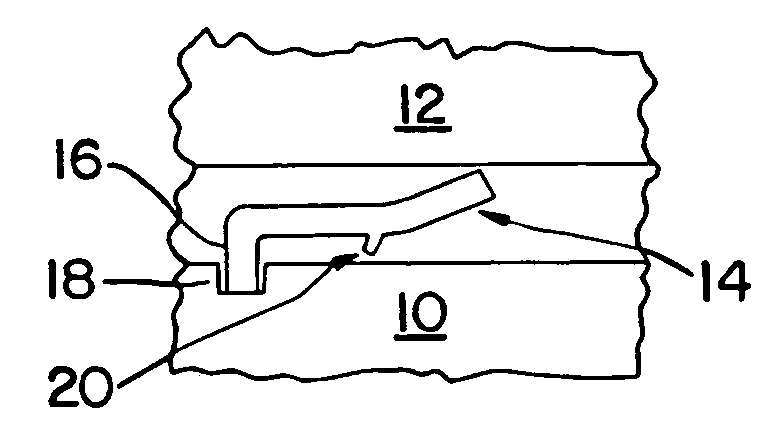
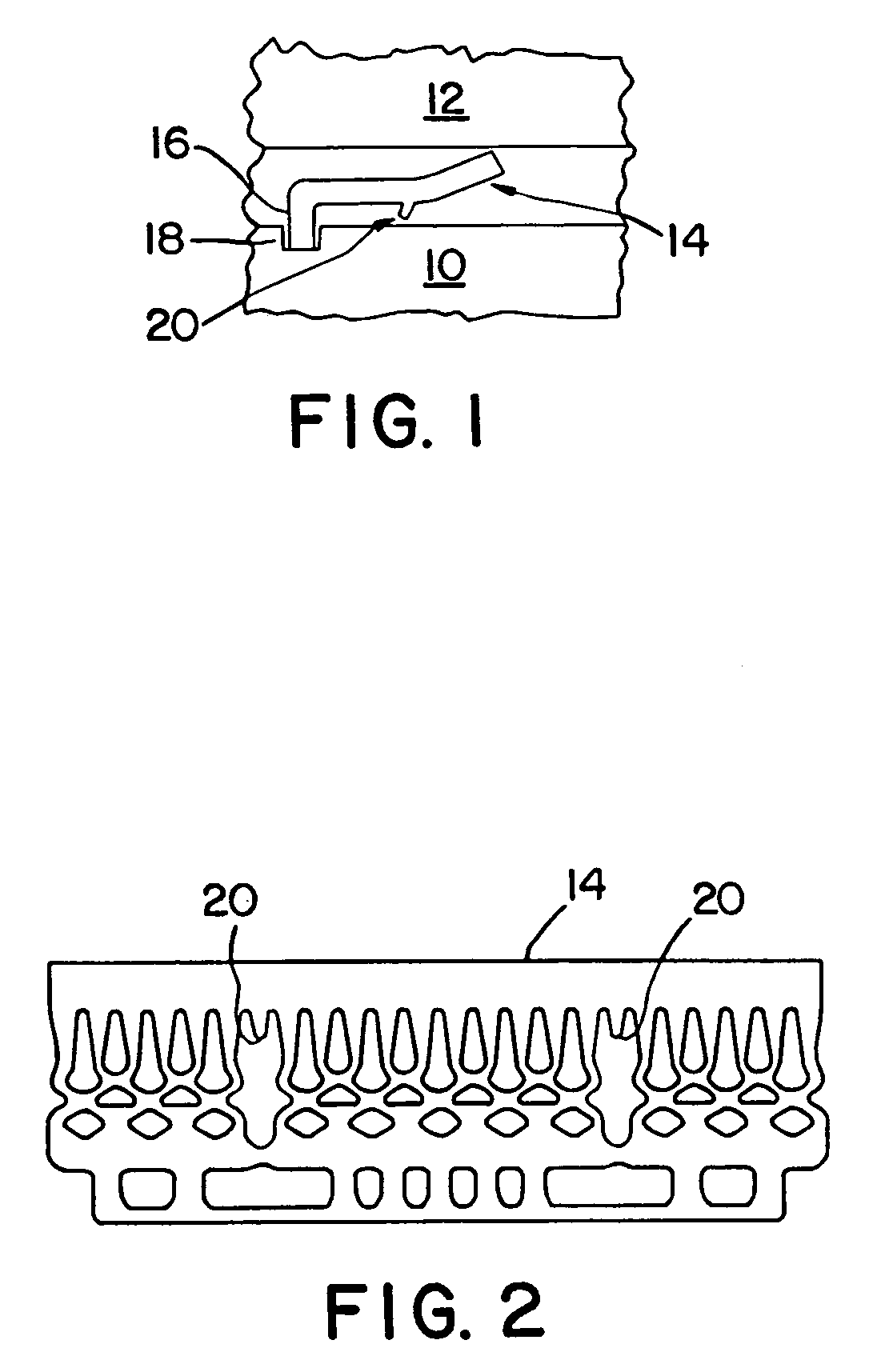
[0025] Referring now to the drawings, FIGS. 1 and 2 illustrate a casting system in accordance with the present invention. The casting system includes a ceramic or refractory metal core 10, a wax die 12 spaced from the core 10, and a refractory metal core 14 positioned between the core 10 and the wax die 12. The refractory metal core 14 may be formed from a material selected from the group consisting of molybdenum, tantalum, niobium, tungsten, alloys thereof, and intermetallic compounds thereof. A preferred material for the refractory metal core 14 is molybdenum and its alloys. If desired, the refractory metal core 14 may be provided with a protective ceramic coating. The refractory metal provides more ductility than conventional ceramic while the ceramic coating, if present, protects the refractory metal during the shell fire step of the investment casting process and prevents dissolution of the core 14 from molten metal.

[0026] The refractory metal core 14 has at least one engagemen...

second embodiment

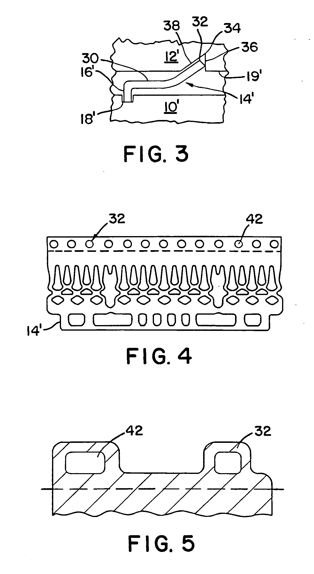
[0029] Referring now to FIGS. 3 and 4, a casting system in accordance with the present invention is illustrated. In this embodiment, the refractory metal core 14′ is used to form a core / shell tie. As can be seen from the figure, the core 14′ has at least one engagement member 16′ at a first end which fits into at least one slot 18′ in the ceramic or refractory metal core 10′. The core 14′ also has a planar central portion 30 and at least one end portion 32 angled with respect to the central portion. If desired, the core 14′ may be provided with a plurality of spaced apart end portions or tabs 32. The end portion(s) 32 at its terminal end fits into at least one slot 34 in the wax die 12′. As shown in FIG. 3, the slot may be triangularly shaped in cross section. Alternatively, the slot may be U-shaped in cross section if a terminal portion of end portion 32 is substantially perpendicular to a surface 19′ of the wax die 12′.

[0030] As can be seen from the figure, each slot 34 may have a...


PUM

PropertyMeasurementUnit
refractoryaaaaaaaaaa
THICKNESSaaaaaaaaaa
melting pointaaaaaaaaaa

Abstract

In accordance with the present invention, a casting system is provided which broadly comprises a core and a wax die spaced from said core, a refractory metal core having a first end seated within a slot in the core and a second end contacting the wax die for positioning the core relative to the wax die, and the refractory metal core having at least one of a mechanism for providing spring loading when closed in the wax die and a mechanism for mechanically locking the wax die to the core.

Description

CROSS-REFERENCE TO RELATED APPLICATION(S) [0001] This application is a divisional application of U.S. patent application Ser. No. 10 / 687,231, filed Oct. 16, 2003, entitled REFRACTORY METAL CORE WALL THICKNESS CONTROL, By James T. Beals et al.BACKGROUND OF THE INVENTION [0002] (1) Field of the Invention [0003] The present invention relates to a casting system for use in forming turbine engine components and to a refractory metal core used therein. [0004] (2) Description of the Related Art [0005] Investment casting is a commonly used technique for forming metallic components having complex geometries, especially hollow components, and is used in the fabrication of superalloy gas turbine engine components. The present invention will be described in respect to the production of superalloy castings, however it will be understood that the invention is not so limited. [0006] Cores used in investment casting techniques are fabricated from ceramic materials which are fragile, especially the ...

Claims


Application Information

Patent Timeline
Patent Type & Authority Applications(United States)
IPC IPC(8): B22C9/04B22D27/04B22C1/00F01D5/18B22C7/02B22C9/10B22C21/14F01D5/28F01D9/02F01D25/00F02C7/00
CPCB22C7/02B22C9/04B22C9/10B22C21/14B22C1/00B22C3/00B22C9/108
Inventor BEALS, JAMES T.DRAPER, SAMUEL D.LOPES, JOSEMURRAY, STEPHEN D.SPANGLER, BRANDON W.
Owner RTX CORP
Why Eureka
Try Eureka