Head mounted display

a display and display body technology, applied in the field of head mounted displays, can solve the problems of cosmetics and the like adhesion to the holding part, display is relatively unsightly, and it is difficult for users to determine the location of buttons or the like in the controller

Active Publication Date: 2006-06-08
NIKON CORP
View PDF69 Cites 209 Cited by
  • Summary
  • Abstract
  • Description
  • Claims
  • Application Information

AI Technical Summary

Benefits of technology

[0017] The present invention was devised in order to solve such conventional problems. The first object of the present invention is to provide a head mounted display which is relatively fre

Problems solved by technology

However, in the case of such conventional head mounted displays, when the display is mounted on the head, the holding part that holds the display part is positioned laterally along the forehead; accordingly, the following problem arises: namely, the display is relatively unsightly.
Furthermore, especially in the case of women, the problem of cosmetics and the like adhering to the holding part also arises.
However, in the case of a head mounted display, since video images are displayed with the line of sight of the user blocked, it is difficult for the user to ascertain where the buttons or the like are located in the controller.
In this case, however, it is not possible to install a very large number of buttons; furthermore, the buttons are installed on a controller that is separate from the main body of the head mounted display.
On the other hand, since different images are seen by both eyes, there is a problem in that concentration on the video image is impossible; furthermore, there are problems of eye fatigue and the like due to visual field

Method used


Image

  • Head mounted display
  • Head mounted display
  • Head mounted display

Examples


Embodiment Construction

[0166] Working configurations of the present invention will be described in detail below with reference to the figures.

(First Working Configuration)

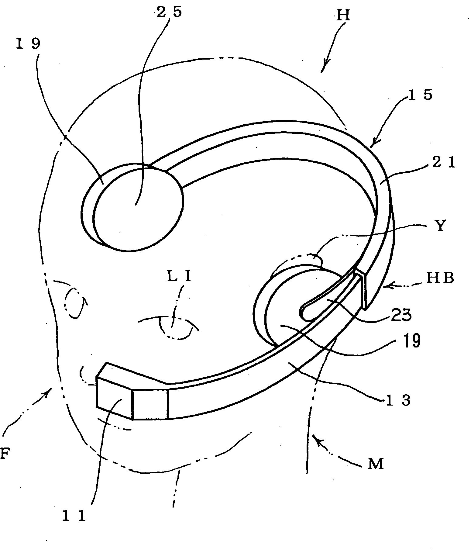
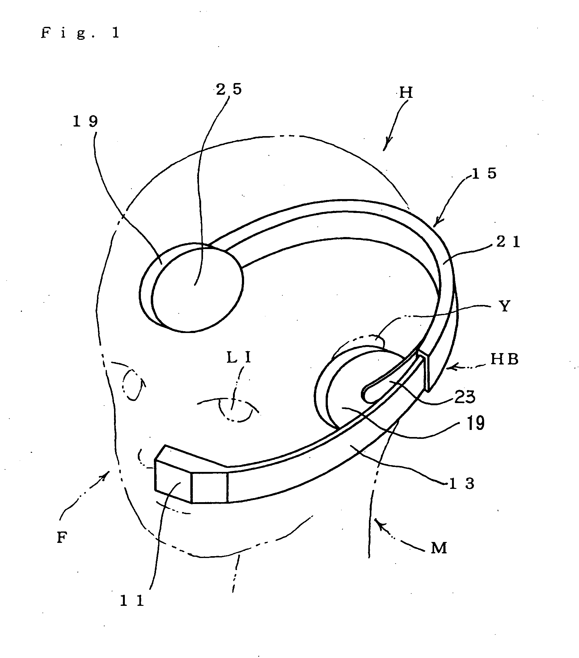
[0167]FIG. 1 shows a first working configuration of the display device of the present invention.

[0168] The display device of this working configuration has a display part 11 constituting display means for displaying images to the wearer M. In this working configuration, the display part 11 displays images only to the left eye L1 of the wearer M. The display part 11 is supported on a mounting part 15 via a supporting part 13 constituting supporting means. The mounting part 15 can be mounted in a position that does not cover the front surface of the head H, i.e., the face F. The mounting part 15 has holding parts 19 in two places disposed on the head H of the wearer M, and a linking part 21 that links the holding parts 19. In this working configuration, the holding parts 19 are fastened to the linking part 21 via connecting parts 23, a...


PUM


Abstract

The head mounted display of the present invention has a display part for displaying images to the wearer, a supporting part which supports the display part, which is fed out into a position in front of as eye from a position that is not located in front of the face, and which is moved from this position in front of as eye into this position that is not located in front of the face, and a mounting part which holds this supporting part, and which is mounted on the wearer in a position that is not located in front of the face, and is constructed so that the supporting part can move past the side of the head along the contour of the head. As a result, a display device is produced which is relatively free of unsightliness with respect to the wearer.

Description

[0001] This is a continuation of PCT International Application No. PCT / JP2003 / 016422 filed on Dec. 22, 2003, which is hereby incorporated by reference.TECHNICAL FIELD [0002] The present invention relates to a head mounted display which allows the observation of video images while mounted on the head. BACKGROUND ART [0003] Conventionally, video display devices which are used to observe video images while mounted on the head have been referred to as head mounted displays. For example, the displays disclosed in Japanese Patent Application Kokai No. H8-320453 and Japanese Patent Application Kokai No. H7-284041 are known as examples of such displays. In the head mounted displays disclosed in these patents, a holding part that holds a display part has a so-called hair band shape, and the display part is held in front of the eyes by mounting this holding part on the forehead. [0004] However, in the case of such conventional head mounted displays, when the display is mounted on the head, th...

Claims


Application Information

Patent Timeline
IPC IPC(8): G09G5/00G02B27/01
CPCG02B27/0176G02B2027/0156
Inventor KATO, SHIGERUOTSUKI, MASAKIMIYAKE, NOBUYUKICHIAKL, KENZO
Owner NIKON CORP
Why Eureka
Try Eureka