
Method of calibrating inkjet print head

a technology of inkjet printing and print head, which is applied in the direction of printing and other printing apparatus, etc., can solve the problems of complex computation, poor printing quality, and more serious deviation

Inactive Publication Date: 2006-06-08
IND TECH RES INST
View PDF5 Cites 22 Cited by
  • Summary
  • Abstract
  • Description
  • Claims
  • Application Information

AI Technical Summary

Benefits of technology

[0007] In view of the foregoing, the invention provides a method of calibrating print heads. It employs a set of specially designed test patterns. By detecting the overlapping state of the test patterns, the method obtains an optimal alignment condition. It achieves the goal of automatically calibrating the print head for alignment, thus solving the problems existing in the prior art.
[0008] To achieve the above objective, the disclosed method of calibrating print heads include the steps o

Problems solved by technology

This will make the deviation more serious.
Therefore, the printing quality will be poor if the print head is not calibrated.
Therefore, it is time-consuming.
The computation is complicated and time consuming.

Method used


Image

  • Method of calibrating inkjet print head
  • Method of calibrating inkjet print head
  • Method of calibrating inkjet print head

Examples


third embodiment

[0030] The widths of the first stripe pattern in the first stripe pattern set and the second stripe pattern in the second pattern are the same as the above-mentioned embodiment. In practice, their widths can be different. As shown in FIG. 8, the invention has wider second stripe patterns 72 than the first stripe patterns 70.

fourth embodiment

[0031] In the test patterns in the fourth embodiment, as shown in FIG. 9, the second pattern 82 is a block pattern and overlaps partially with the first stripe pattern set 80. This can avoid the situation shown in FIG. 10. The drawing shows that the first stripe pattern set 90 with horizontal lines and the second stripe patterns 94 of the second pattern 92 overlap in the horizontal direction. When using the average reflectance of the test patterns to determine the overlapping state of the first stripe pattern set 90 and the second pattern 92, there will not be significant differences in the reflected signal, resulting in difficult decisions.

[0032] It should be mentioned that FIGS. 11A to 11J show the theoretical variations of the reflection signals of the test patterns detected by the photo sensor 99. As the photo sensor 99 passes through the test patterns, it detects the reflection signals of the test patterns, obtaining many sets of reflection signals. Suppose the test pattern pro...


PUM


Abstract

A method of calibrating inkjet print head is disclosed to print a specially designed test pattern, including a plurality of first stripe patterns and several second patterns continuously printed and overlapped with each other. The overlapping between the first stripe patterns and the second patterns is checked. One overlapping state is extracted to find an optimal alignment condition, thereby calibrating the inkjet print head and enhancing the printing quality.

Description

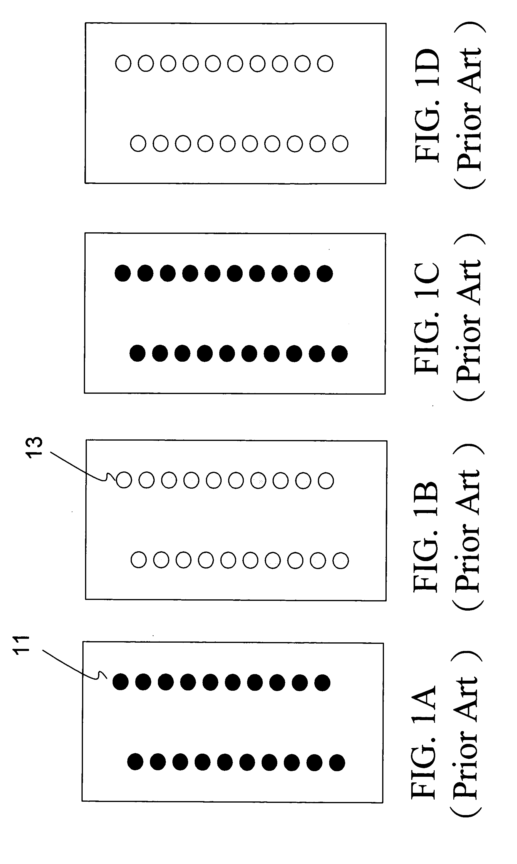
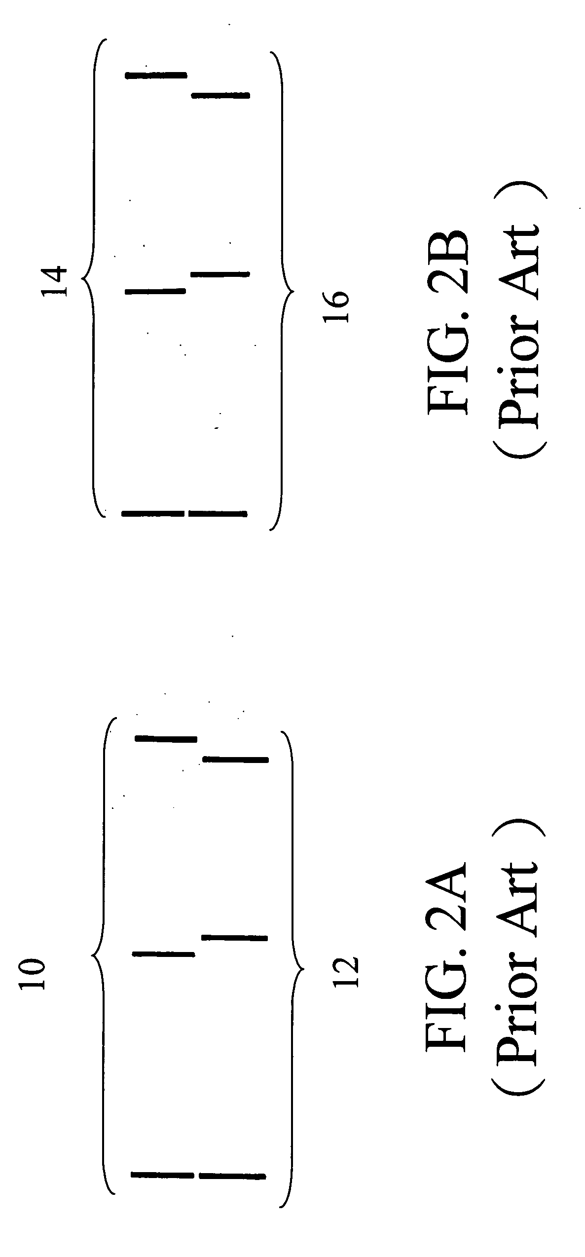
BACKGROUND OF THE INVENTION [0001] 1. Field of Invention [0002] The invention relates to a method of calibrating an inkjet print heads and, in particular, to a method of calibrating the print head of an inkjet printer by obtaining an optimal alignment condition through the retrieval of an overlapping state of test patterns. [0003] 2. Related Art [0004] An inkjet printer for printing images and documents which are achieved by appropriate image and halftone processing, letting the print heads to have a reciprocal motion over a medium, and ejecting ink droplets at desired location through numerous nozzles. Generally speaking, a print head on a cartridge has numerous nozzles arranged in parallel, as shown in FIGS. 1A to 1D representing the print heads of black, cyan, magenta, and yellow colors. To achieve the photographic quality printing, the print heads have to be aligned and calibrated before reciprocal printing. Such calibration includes the reciprocal printing of the nozzles 11, or...

Claims


Application Information

Patent Timeline
IPC IPC(8): B41J29/393
CPCB41J29/393
Inventor HSU, JUEI TSANGLO, MENG-FENHAN, HSIAO-YU
Owner IND TECH RES INST
Learn More