Microscope

a microscope and optical fiber technology, applied in the field of microscopes, can solve the problem of no technology to make such an improvemen

Inactive Publication Date: 2006-06-08
JASCO CORP
View PDF8 Cites 2 Cited by
  • Summary
  • Abstract
  • Description
  • Claims
  • Application Information

AI Technical Summary

Benefits of technology

[0008] The present invention was conceived in light of the above problem of the prior art,

Problems solved by technology

To follow such spectral changes, the measurement speed of microscopes needs to be impr

Method used


Image

  • Microscope
  • Microscope
  • Microscope

Examples


Embodiment Construction

[0026] A preferred embodiment will be described below by referring to the drawings.

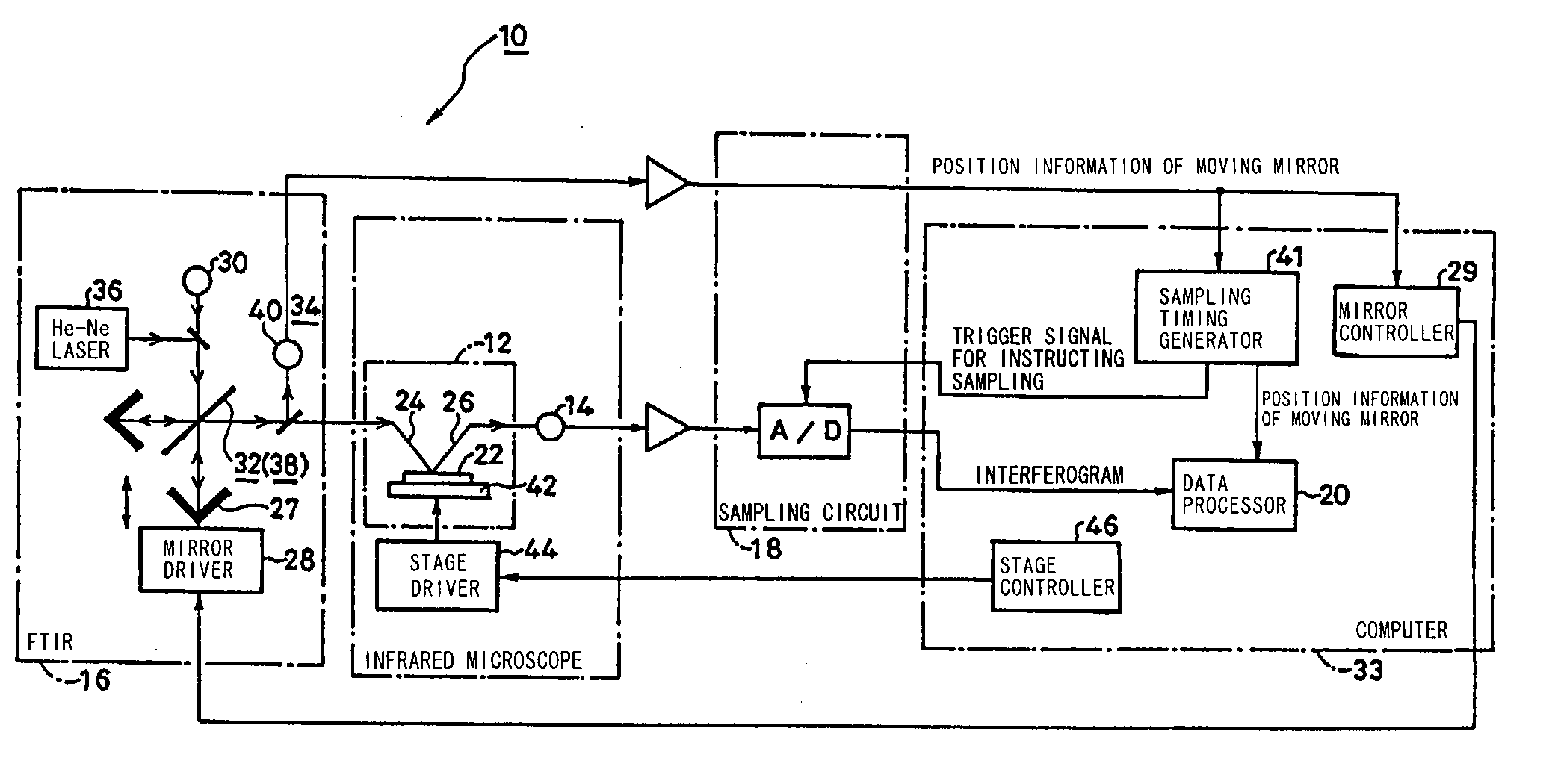
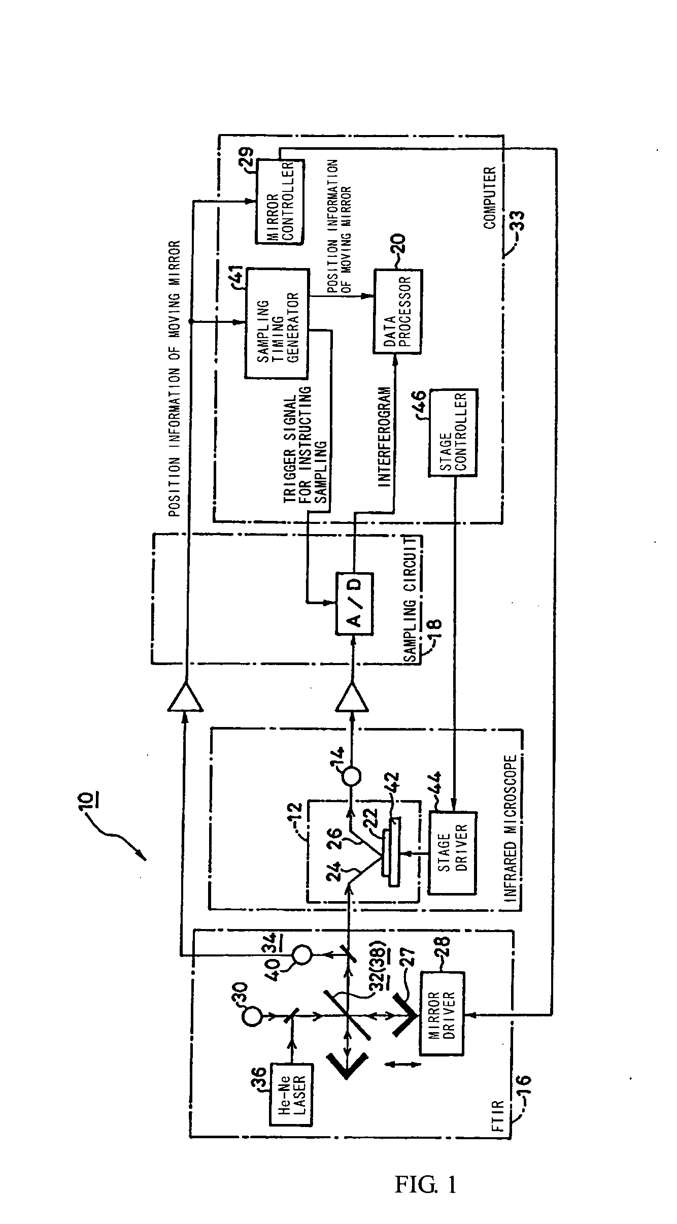
[0027]FIG. 1 shows an outlined structure of a multi-channel infrared microscope 10 according to an embodiment of the present invention.

[0028] In addition to an infrared microscope having a microscope unit (light sampler) 12 and a multi-element infrared detector (multi-element detector) 14, the multi-channel infrared microscope (microscope) 10 includes a Fourier transform infrared spectrophotometer (FTIR) 16, a sampling circuit (data sampler) 18, and a data processor 20.

[0029] The microscope unit 12 illuminates a measurement area of a sample 22 with interference light 24 and obtains interference light 26 coming from the measurement area.

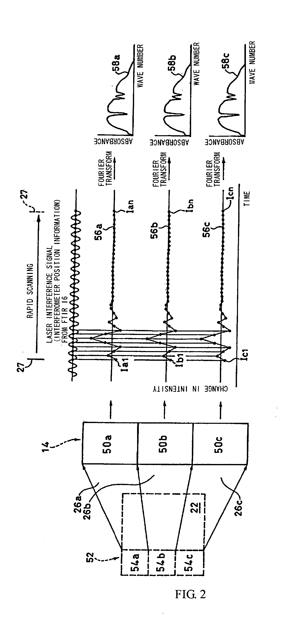
[0030] The multi-element infrared detector 14 has a plurality of photoelectric elements disposed in one dimension and detects the interference light 26 coming from the measurement area.

[0031] An advantageous feature of the present invention is that a temporal chang...


PUM


Abstract

A microscope comprising: a light sampler for collecting light from a measurement area of a sample; a multi-element detector having a plurality of photoelectric elements, for detecting the light collected by the light sampler, each photoelectric element corresponding to a minute measurement region in the measurement area with one-to-one correspondence; a Fourier transform spectrophotometer as a spectroscope; a data sampler for concurrently sampling intensity data sent from each photoelectric element of the multi-element detector at a timing determined by the Fourier transform spectrophotometer; and a data processor for obtaining time-resolved spectrum data for each minute measurement region according to temporally changed interference light data obtained by the data sampler.

Description

RELATED APPLICATIONS [0001] This application claims priority to the Japanese Patent Application 2004-352556 dated on Dec. 6, 2004 and is hereby incorporated with reference for all purposes. BACKGROUND OF THE INVENTION [0002] 1. Field of the Invention [0003] The present invention relates to microscopes, and more particularly, to a mechanism therein for obtaining a time-resolved spectrum. [0004] 2. Prior Art [0005] Time-resolved measurement apparatuses are used to measure temporal changes in samples. In the time-resolved measurement apparatuses, the entire sample is illuminated with interference light sent from an interferometer, and interference light coming from the sample is detected to obtain the temporally changed spectrum (for example, see Japanese Unexamined Patent Application Publication No. Hei-5-223640). [0006] Recently, time-resolved measurement is also demanded for microscopes that perform imaging analysis of minute measurement regions. [0007] In time-resolved measurement,...

Claims


Application Information

Patent Timeline
IPC IPC(8): G01B9/02G01J3/45G01N21/27G01N21/35G01N21/3563G02B21/00
CPCG01J3/2889G01J3/453G02B21/0096
Inventor KOSHOUBU, JUN
Owner JASCO CORP
Why Eureka
Try Eureka