Optical deflection device and optical deflection method that control occurrence of alignment defect

a technology alignment defect, which is applied in the direction of instruments, non-linear optics, optics, etc., can solve the problems of difficult to achieve small optical deflection device, limited use and difficulty in making the speed of response faster to the order of sub-milliseconds, so as to speed up the light path shift operation and improve the reliability of optical deflection device. , the effect of speeding up the operation of light path

Inactive Publication Date: 2006-06-08
RICOH KK
View PDF3 Cites 9 Cited by
  • Summary
  • Abstract
  • Description
  • Claims
  • Application Information

AI Technical Summary

Benefits of technology

[0022] It is another and more specific object of the present invention to speed up the light path shift operation by an optical deflection element having a simplified construction, and to control occurrence of alignment defect caused by repeated use so as to improve reliability of the optical deflection device.
[0110] Accordingly, in the optical deflection step, the direction of the electric field formed in the liquid crystal layer is switched by applying the ac voltage of the deflection frequency to the pair of electrodes. Also, the optical deflection direction by the optical deflection element is switched by the switching of the electric field direction. In addition, in the application stop step, when starting the operation of switching the optical deflection direction of the optical deflection element, the pulsed dc voltage is intermittently applied before applying the ac voltage of the deflection frequency. Consequently, the orientation state of the liquid crystal molecules is temporarily disturbed throughout the liquid crystal layer. Thereafter, by applying the ac voltage of the deflection frequency, it is possible to arrange the liquid crystal molecules in the optical deflection direction.

Problems solved by technology

For this reason, the present situation is that it is difficult to achieve smaller optical deflection devices, and the use of optical deflection devices is limited since the materials are expensive.
However, with the technique disclosed in Japanese Laid-Open Patent Application No. 6-18940, for example, it is difficult to make the speed of response faster to the order of sub-milliseconds, since a nematic liquid crystal is used for the liquid crystal material.
However, since a liquid crystal material in a smectic A phase does not produce spontaneous polarization, it is difficult to make the speed of response high enough.
As described above, the optical deflection devices aimed at simplifying the constructions and miniaturization have problems in that it is difficult to speed up the light path shift operations because of the characteristics of the liquid crystal materials used.
With the above-described technique, light losses can be reduced, but problems arise such as occurrence of vibration and noise, and increase in the size of the apparatus.
However, with the technique described in Japanese Laid-Open Patent Application No. 6-324320, the construction for driving the optical deflection element becomes complicated, which leads to high cost.
However, the technique disclosed in Japanese Laid-Open Patent Application No. 10-133135 requires a comparatively large transparent piezoelectric element, and thus the cost of the apparatus is increased.
As described above, in the conventional techniques, it is impossible for the optical deflection devices aimed for simplifying the constructions and miniaturization to sufficiently speed up the light path shift operations.
Also, the optical deflection devices intended to speed up the light path shift operations have problems such as complexity of the constructions of the apparatuses, increase in cost caused by the complexity of the constructions of the apparatus, and increase in the sizes of the apparatuses.
The director of the liquid crystal molecules in the clouded part is irregular, and it is impossible to obtain a good light path shift function with the clouded optical deflection element.
Such white turbidity may occur due to such as influence of an external electric field while the operation of the optical deflection element is suspended for a long time or even for a short period of time.
In addition, with the optical deflection element where liquid crystal molecules being greatly disturbed though white turbidity does not occur, there is fear that reliability is degraded.
The optical deflection operation with white turbidity remaining causes light scattering and reduction of reliability through growth of alignment defect.

Method used


Image

  • Optical deflection device and optical deflection method that control occurrence of alignment defect
  • Optical deflection device and optical deflection method that control occurrence of alignment defect
  • Optical deflection device and optical deflection method that control occurrence of alignment defect

Examples


examples

[0260] A description will be given of examples of the present invention. In the examples, three kinds of optical deflection elements A, B and C are prepared. As will be described in Examples 1 through 4 and Comparative Examples 1 and 2, the evaluations of variation in performance through repeated use are made by varying the application method of a voltage to the optical deflection elements A, B and C.

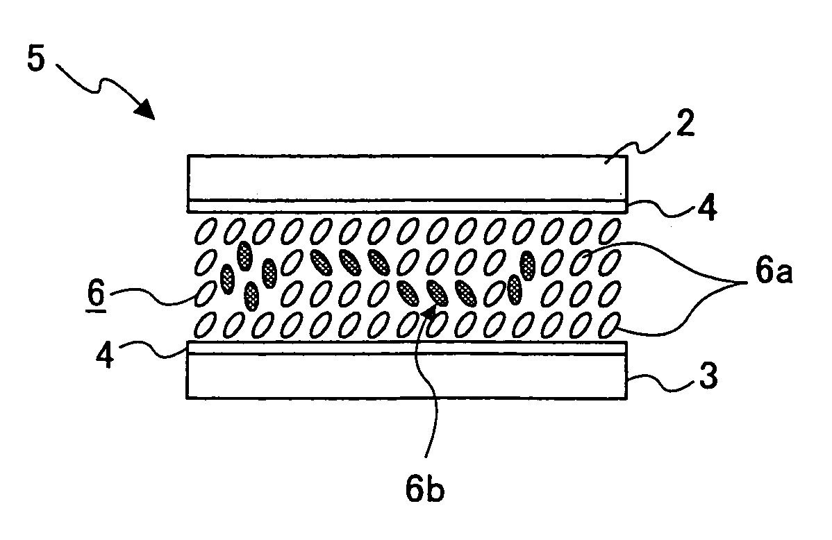
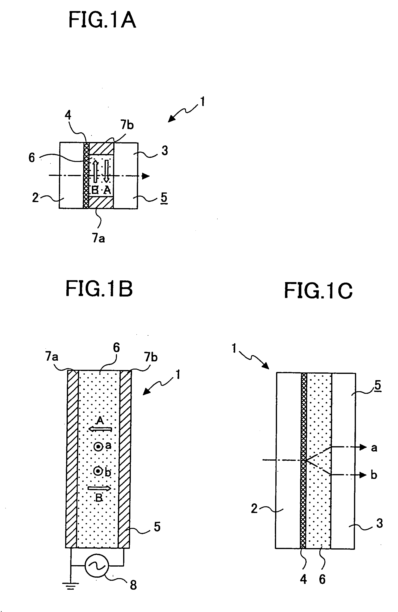
[0261] First, a surface of a glass board (the boards 2 and 3), having the size of 3 cm×4 cm with the thickness of 1 mm, was treated with a perpendicular orientation film JALS2021-R2 (manufactured by JSR Corporation) so as to form a perpendicular orientation film (the orientation film 4) on one side of the glass board. Two of such glass boards were bonded together with the perpendicular orientation films inside while interposing therebetween two aluminum electrode sheets (the electrodes 7a and 7b) as spacers, each of the aluminum electrode sheets having the thickness of 50 μm, the width...

example 1

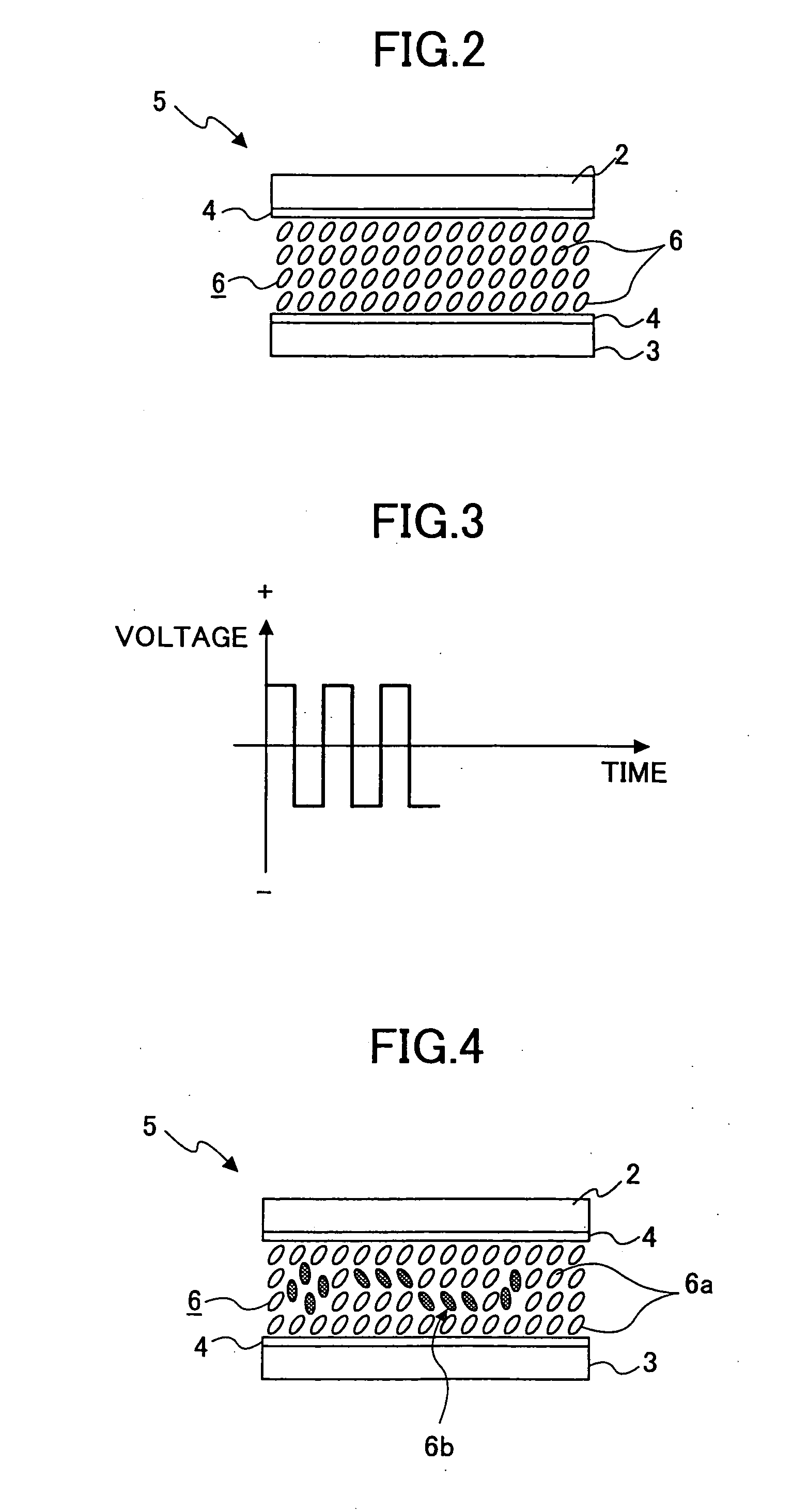
[0268] In Example 1, using the optical deflection element A, the ac voltage of ±200 V and 100 Hz, which was similar to the pixel shift driving, was applied for 40 minutes in a similar manner. Thereafter, an ac voltage of +100 V and 1 kHz was applied for one minute before stopping the optical deflection operation. Then, the orientation state of the liquid crystal layer thereafter was observed.

[0269] As a result, in the Example 1, white turbidity was not developed in the vicinities of the electrodes. Although a similar optical deflection operation was repeated thereafter, white turbidity was not developed.

example 2

[0270] In Example 2, using the optical deflection element A, the ac voltage of ±200 V and 100 Hz, which was similar to the pixel shift driving, was applied for 40 minutes in a similar manner. Then, a pulsed dc voltage of +200 V is applied ten times in one minute and stopped. Then, the orientation state of the liquid crystal thereafter was observed.

[0271] Consequently, in Example 2, white turbidity was not developed in the vicinities of the electrodes. Thereafter, though the similar optical deflection operation was repeated, white turbidity was not developed.


PUM

PropertyMeasurementUnit
driving frequencyaaaaaaaaaa
deflection frequencyaaaaaaaaaa
frequencyaaaaaaaaaa

Abstract

An optical deflection device includes an optical deflection element having a pair of transparent boards arranged in a mutually opposing manner. A liquid crystal layer is filled between the boards and forms a chiral smectic C phase. An orientation film orients liquid crystal molecules in the liquid crystal layer in a substantially perpendicular direction with respect to the liquid crystal layer. Electrodes generate an electric field in a substantially parallel direction with respect to the liquid crystal layer. A first voltage application part applies, to the electrodes, an ac voltage of a deflection frequency switching the optical deflection direction of the optical deflection element. A second voltage application part applies, to the electrodes, an ac voltage of a higher frequency than the deflection frequency. A stop process part causes the second voltage application part to apply the ac voltage of the higher frequency than the deflection frequency after causing the first voltage application part to apply the ac voltage of the deflection frequency, when stopping an operation of switching the optical deflection direction of the optical deflection element.

Description

BACKGROUND OF THE INVENTION [0001] 1. Field of the Invention [0002] The present invention relates to optical deflection devices and optical deflection methods. [0003] 2. Description of the Related Art [0004] Conventionally, known optical deflection devices deflecting and emitting incident light by using optical deflection elements include electro-optical devices that use materials having great primary electro-optical effect (Pockels effect), such as KH2PO4(KDP), NH4H2PO4(ADP), LiNbO3, LiTaO3, GaAs and CdTe, and materials having great secondary electro-optical effect, such as KTN, SrTiO3, CS2 and nitrobenzene, and include acousto-optical devices that use materials such as glass, silica and TeO2 (for example, refer to “Optoelectronic Device” edited by Masaharu Aoki, Shokodo). Also, there are proposed various optical deflection devices that use optical deflection elements including liquid crystal materials. [0005] For example, as disclosed in Japanese Laid-Open Patent Applications No. ...

Claims


Application Information

Patent Timeline
Patent Type & Authority Applications(United States)
IPC IPC(8): G02F1/29G02F1/139G02F1/141G02F1/31
CPCG02F1/1393G02F1/141G02F1/31
Inventor MATSUKI, YUMISUGIMOTO, HIROYUKITOKITA, TOSHIAKINIMURA, SHIGEAKIKOBAYASHI, MASANORITAKIGUCHI, YASUYUKI
Owner RICOH KK
Why Eureka
Try Eureka