Capacitor microphone unit and capacitor microphone

a capacitor microphone and microphone technology, applied in the direction of electrical transducers, transducer types, piezoelectric/electrostrictive transducers, etc., can solve the problems of reducing the frequency and reducing the frequency response of the microphone unit. , to achieve the effect of reducing the frequency respons

Inactive Publication Date: 2006-06-08
AUDIO-TECHNICA
View PDF2 Cites 16 Cited by
  • Summary
  • Abstract
  • Description
  • Claims
  • Application Information

AI Technical Summary

Benefits of technology

[0017] The elastic and conductive shock absorber protects the internal components against vibrations and shocks, reduce vibration noises, and shields the microphone unit against external electromagnetic waves.

Problems solved by technology

As a result, vibration noises will be produced.
However, they do not suggest to provide a member preventing vibration noises in the microphone unit.
One of the reasons is that it is very difficult to incorporate a shield structure for external electromagnetic waves in the microphone unit together with the vibration noise preventing member.
However, since the unit case and the grounding electrode are in point contact with each other, they may be unstable in their electric connection and have a complicated structure.
Up to now, no microphone having such a shield structure is actually available.

Method used


Image

  • Capacitor microphone unit and capacitor microphone
  • Capacitor microphone unit and capacitor microphone
  • Capacitor microphone unit and capacitor microphone

Examples


Embodiment Construction

[0025] The invention will be described with reference to embodiments shown in FIG. 1 to FIG. 4.

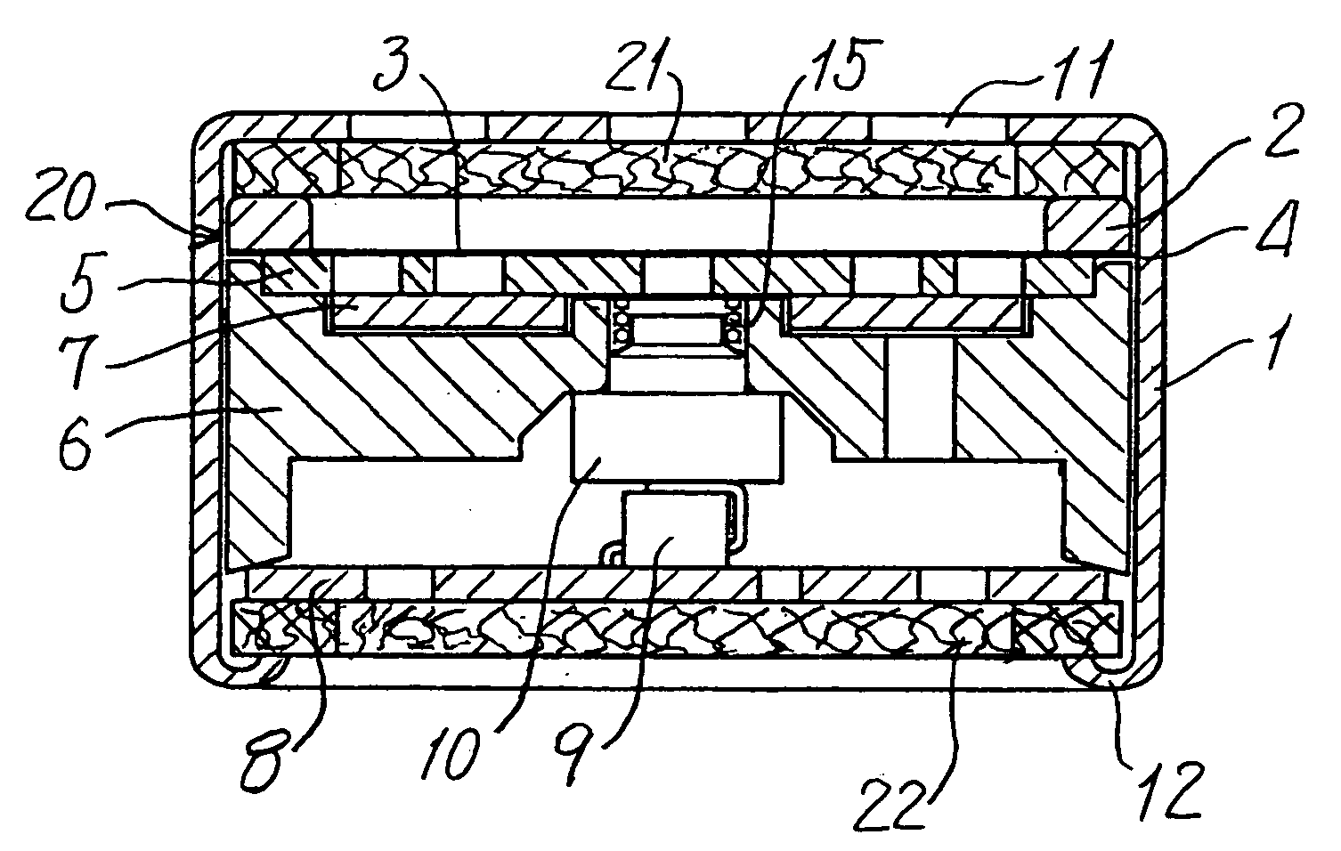
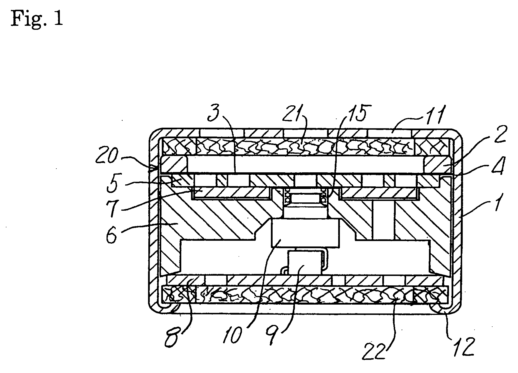
[0026] Referring to FIG. 1 and FIG. 2, a unit case 1 is cylindrical and has a front mesh 11 (called the “mesh 11”), via which sounds are introduced. The mesh 11 serves as a front part of a capacitor microphone. A shock absorber 21 is housed in the unit case 1 nearest the mesh 11. The shock absorber 21 is made of a conductive material, is annular, and is slightly thinner than the unit case 1, so that the shock absorber 21 does not extend over the mesh 11. The conductive material may be metal threads regularly or irregularly woven in the shape of a fabric. SUI-78-5010T produced by Taiyou Wire Netting Co., may be usable as the shock absorber. Alternatively, the shock absorber may be made of conductive sponges, conductive rubbers, or the like.

[0027] In the unit case 1, a diaphragm assembly 20 is placed on the shock absorber 21. The diaphragm assembly 20 includes an annular diaphragm support ...


PUM


Abstract

A capacitor microphone unit which includes a diaphragm assembly constituted by a diaphragm and a diaphragm support, a fixed electrode facing with the diaphragm with a clearance and functioning as a capacitor together with the diaphragm, a unit case housing components including the diaphragm assembly and the fixed electrode, and an elastic and conductive shock absorber provided between the diaphragm assembly, the fixed electrode and the unit case.

Description

CROSS REFERENCE TO RELATED APPLICATIONS [0001] This application is based upon and claims the benefit of priority from prior Japanese Patent Application No. 2004-355,234 filed on or around Dec. 8, 2004; the entire contents of which are incorporated by reference herein. BACKGROUND OF THE INVENTION [0002] 1. Field of the Invention [0003] This invention relates to a capacitor microphone unit and a capacitor microphone which are designed to prevent vibration noises. [0004] 2. Description of the Related Art [0005]FIG. 5 and FIG. 6 of the accompanying drawings show an example of a capacitor microphone unit of the related art. The capacitor microphone unit includes a cylindrical unit case 1, which has a front mesh 11. The front mesh 11 is positioned at a front part of the microphone unit (the front mesh 11 will be called the “mesh 11” hereinafter). Voice signals are introduced into the microphone unit via the mesh 11. A diaphragm assembly 20 is positioned nearest the mesh 11, and is constit...

Claims


Application Information

Patent Timeline
Patent Type & Authority Applications(United States)
IPC IPC(8): H04R25/00H04R17/02H04R19/04
CPCH04R19/016
Inventor AKINO, HIROSHI
Owner AUDIO-TECHNICA
Why Eureka
Try Eureka