Regenerative thermal oxidizer

a regenerative thermal oxidizer and oxidizer technology, applied in the direction of combustion types, heating types, stoves or ranges, etc., can solve the problems of materially affecting the efficiency of regenerative thermal oxidizers, short circuiting of oxidizers, and potential for polluting the environment, and achieve the effect of relatively constant pressure of fluid through the regenerative thermal oxidizer

Inactive Publication Date: 2006-06-08
THORNTON LYMAN L
View PDF12 Cites 14 Cited by
  • Summary
  • Abstract
  • Description
  • Claims
  • Application Information

AI Technical Summary

Benefits of technology

[0008] A regenerative thermal oxidizer system for use in processing a contaminated fluid. The system includes a combustion chamber, a system fluid feed duct, and at least a first and a second regenerator chambers in fluid communication with the combustion chamber. A regenerator half-chamber is provided in fluid and thermal communication with the combustion chamber. A first flow control element is provided for controlling a flow of fluid from the system fluid feed duct to the first regenerator chamber, and a second flow control element is provided for controlling a flow of fluid from the system fluid feed duct to the second regenerator chamber. An intermittent supply duct connects the system fluid feed duct to the regenerator half-chamber. A third flow control element controls flow of system feed fluid through the intermittent supply duct. Feed fluid is directed either to one of the first and second regen

Problems solved by technology

Industrial process emissions often contain combustible contaminants and/or odors that, if released to atmosphere, have a potential for polluting the environment.
One problem that materially affects the efficiency of regenerative thermal oxidizers is short circuiting of the oxidizer by contaminated emissions incident to opening and closing of the valves required for control of fluid flow to and from the regenerators.
The resulting pressure variations place excessive loads on the fluid moving equipment and are unacceptab

Method used


Image

  • Regenerative thermal oxidizer
  • Regenerative thermal oxidizer
  • Regenerative thermal oxidizer

Examples


Embodiment Construction

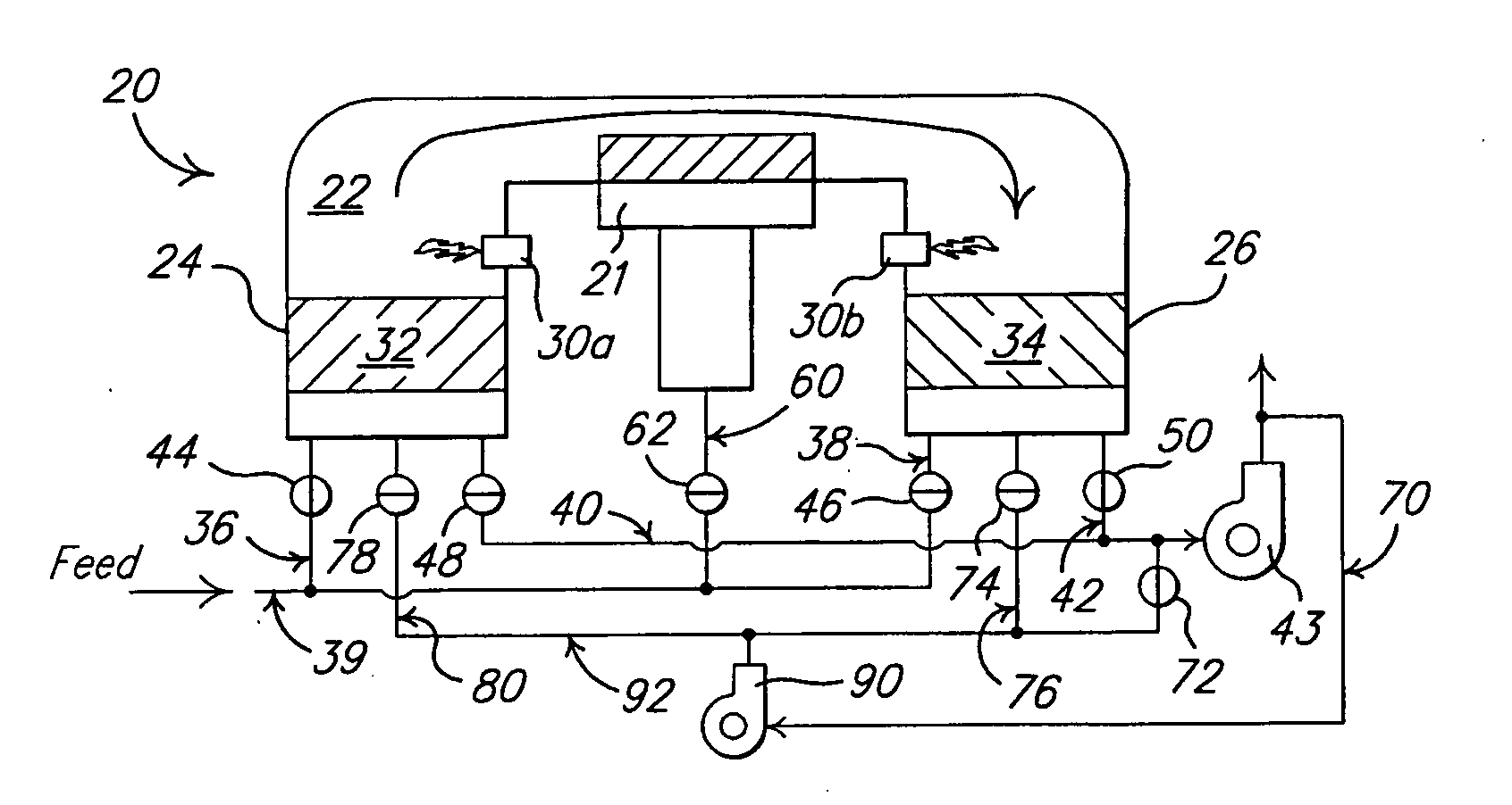
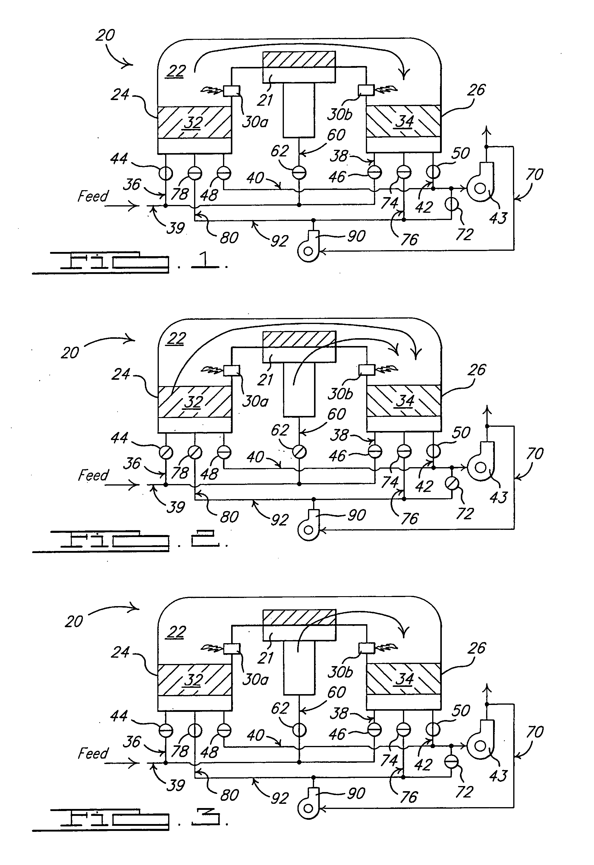
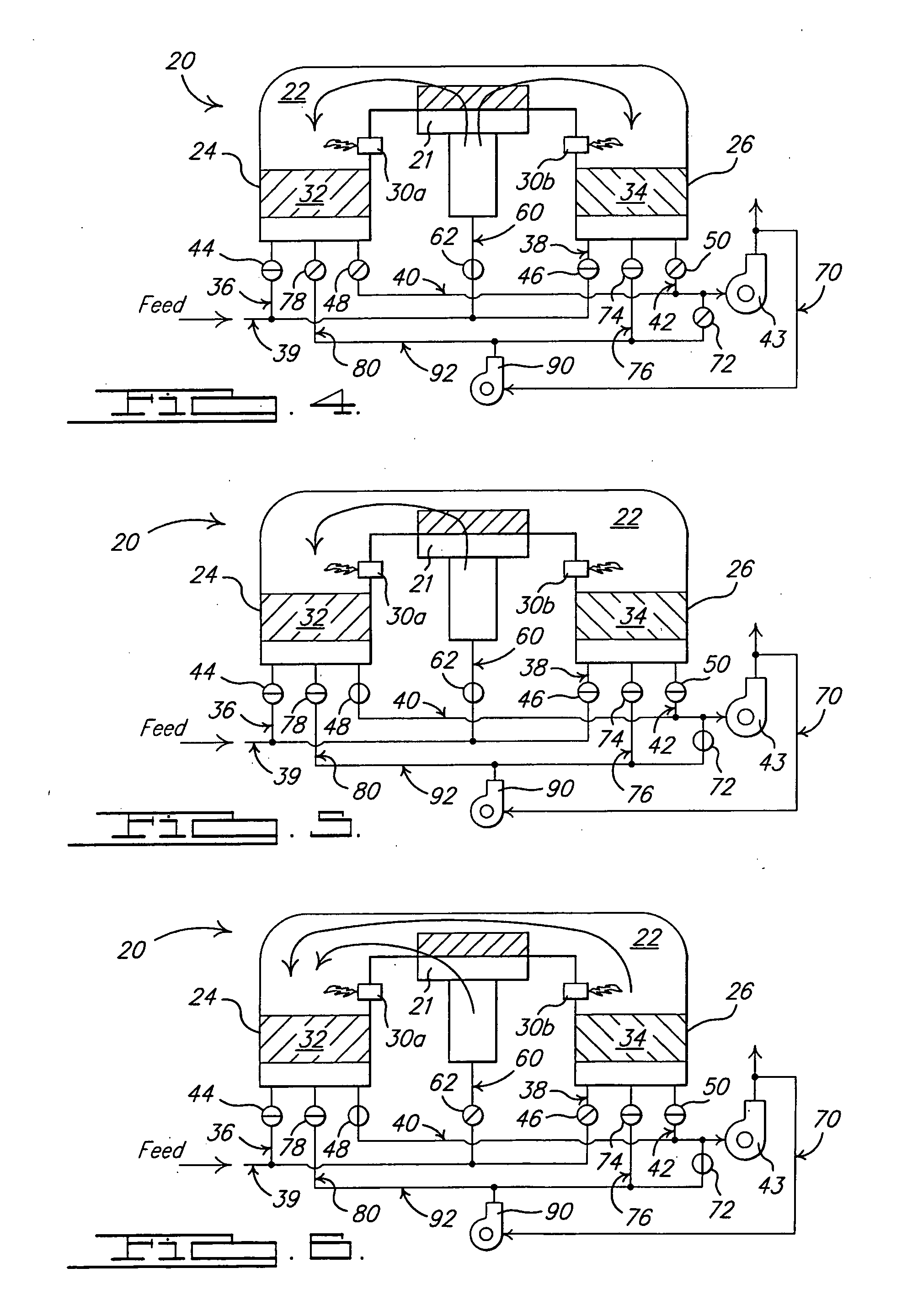
[0011]FIGS. 1-12 show a schematic representation of one embodiment of a regenerative thermal oxidizer system in accordance with the present invention, although the present invention is applicable to oxidizer systems having other known configurations. As seen in FIGS. 1-12, a two chamber regenerative oxidizer 20 comprises a common combustion chamber 22 overlying a pair of conventional segregated regenerative chambers 24 and 26. The combustion chamber 22 is provided with one or more conventional burners 30a and 30b. In the embodiment shown, a first burner 30a is provided in combustion chamber 22 proximate regenerative chamber 24 and a second burner 30b is provided in combustion chamber 22 proximate regenerative chamber 26. While the embodiment of the oxidizer disclosed herein shows burners 30a and 30b positioned proximate chambers 24 and 26, the burners are not necessarily positioned proximate chambers 24 and 26, and may be positioned at any of a variety of alternative locations withi...


PUM


Abstract

A regenerative thermal oxidizer system (20) for use in processing a contaminated fluid. The system includes a combustion chamber (22), a contaminated fluid feed duct (39), and at least a first (24) and a second (26) regenerator chambers in fluid communication with the combustion chamber (22). A regenerator half-chamber (21) is provided in fluid and thermal communication with the combustion chamber (22). A first flow control element (44) is provided for controlling a flow of fluid from the system fluid feed duct (39) to the first regenerator chamber (24), and a second flow control element (46) is provided for controlling a flow of fluid from the system fluid feed duct (39) to the second regenerator chamber (26). An intermittent supply duct (60) connects the system fluid feed duct (39) to the regenerator half-chamber (21). A third flow control element (62) controls flow of system feed fluid through the intermittent supply duct (60). Feed fluid is directed either to one of the first (24) and second (26) regenerator chambers or to the half-chamber (21) prior to flowing into the combustion chamber (22) so that the fluid is are pre-heated prior to entering the combustion chamber (21).

Description

CROSS REFERENCE TO RELATED APPLICATIONS [0001] This application claims the benefit of provisional application Ser. No. 60 / 632,907, filed on Dec. 3, 2004.BACKGROUND OF THE INVENTION [0002] The present invention relates to the treatment of contaminant laden industrial process emissions and, more particularly, to a ducting and valving system that directs and controls the flow of such emissions to and through a regenerative oxidizer. [0003] Industrial process emissions often contain combustible contaminants and / or odors that, if released to atmosphere, have a potential for polluting the environment. Thermal and / or catalytic oxidizers increase the temperature of such process emissions to a temperature above the ignition temperature of the contaminants therein so as to oxidize the contaminants. [0004] One type of thermal oxidizer is a regenerative thermal oxidizer (“RTO”). The basic components of a regenerative thermal oxidizer are a combustion chamber, at least two separate beds (or cham...

Claims


Application Information

Patent Timeline
IPC IPC(8): F24C15/10
CPCF23G7/068
Inventor THORNTON, LYMAN L.
Owner THORNTON LYMAN L
Why Eureka
Try Eureka