
LGA socket connector with floating cover

Inactive Publication Date: 2006-06-08
HON HAI PRECISION IND CO LTD
View PDF3 Cites 9 Cited by
  • Summary
  • Abstract
  • Description
  • Claims
  • Application Information

AI Technical Summary

Benefits of technology

[0007] In order to resolve the existing issues encountered by the industry, the inventor provides the following solutions so as to overcome the shortcoming of the existing design. According to one of the preferred embodiments, an electrical connector assembly includes an insulative housing having a base with a top mating interface thereof. A plurality of passageways is arranged in rows and extends through the base from the top mating interface, with a plurality of terminals inserted into the corresponding passageways. The terminals have upper connecting portions with at distal ends thereof upper mating sections extending upwardly from the mating interface. The upper connecting portions of at least two adjacent terminals, in a same row, are configured to have projections, from a top view, at least partly overlapped. A floating cover is resiliently and movably mounted above the top mating interface of the base, and defines at least one slot therethrough extending in a row direction along which, from a top view, the whole upper connecting portions essentially direct to. The slot is further configured to allow for the upper mating sections of the at least two adjacent terminals to be simultaneously extend through the slot when the floating cover is pressed downwardly to engage with the base. Thus, no damage will bring to the at least two terminals that have overlapped configuration.

Problems solved by technology

Since the terminals have portions thereof exposed outside of the base, the terminals may be readily damaged by improper external force, especially during transporting process.
This will readily result in electrical connection failure between the chip package and the LGA socket.
As such, it is difficult for these overlapped terminals to be separated therefrom or accommodated with the holes one by one.
In other words, such conventional floating cover member is not capable of effectively protecting the overlapped terminals from being damaged, especially during the transporting process.

Method used


Image

  • LGA socket connector with floating cover
  • LGA socket connector with floating cover
  • LGA socket connector with floating cover

Examples


Embodiment Construction

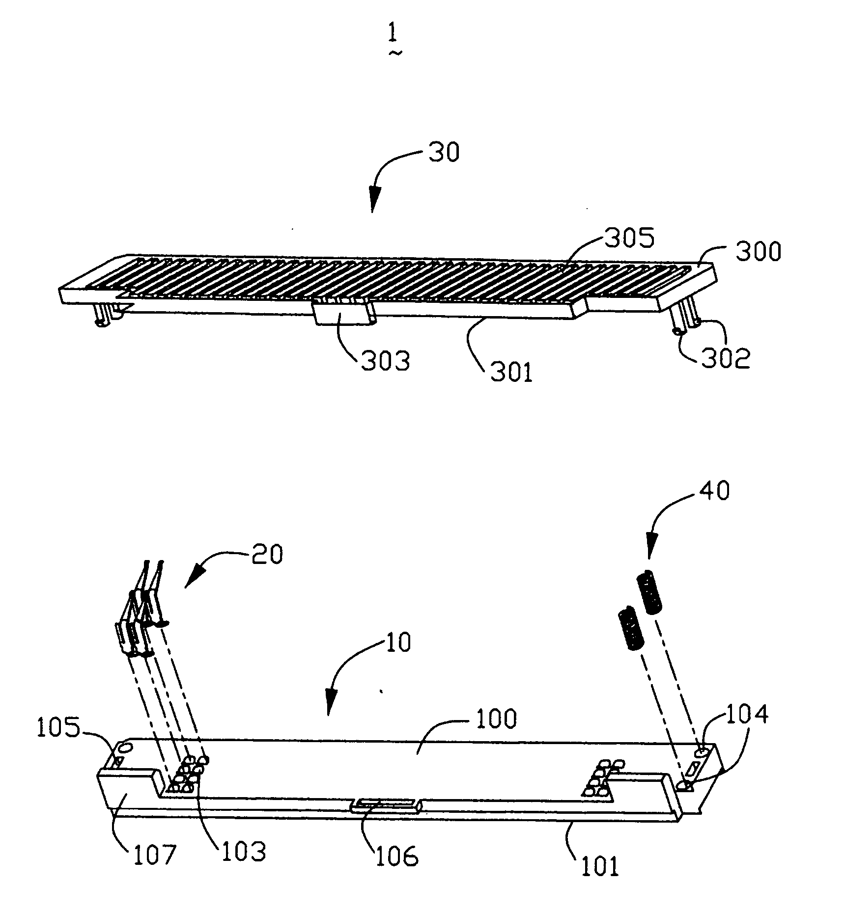
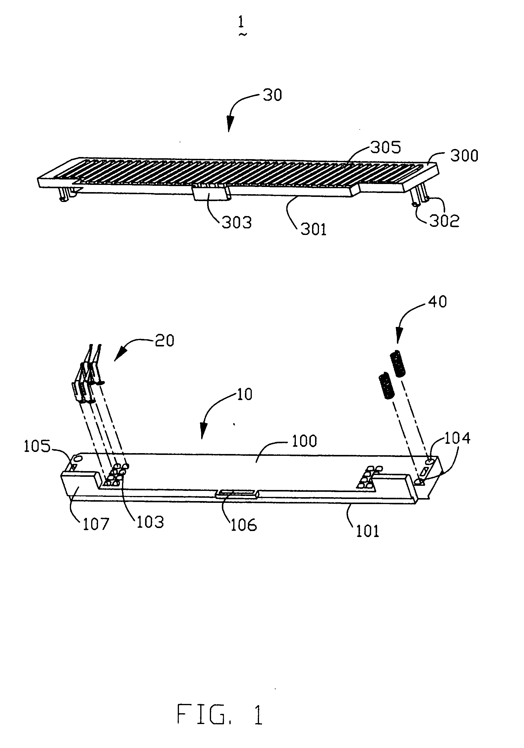
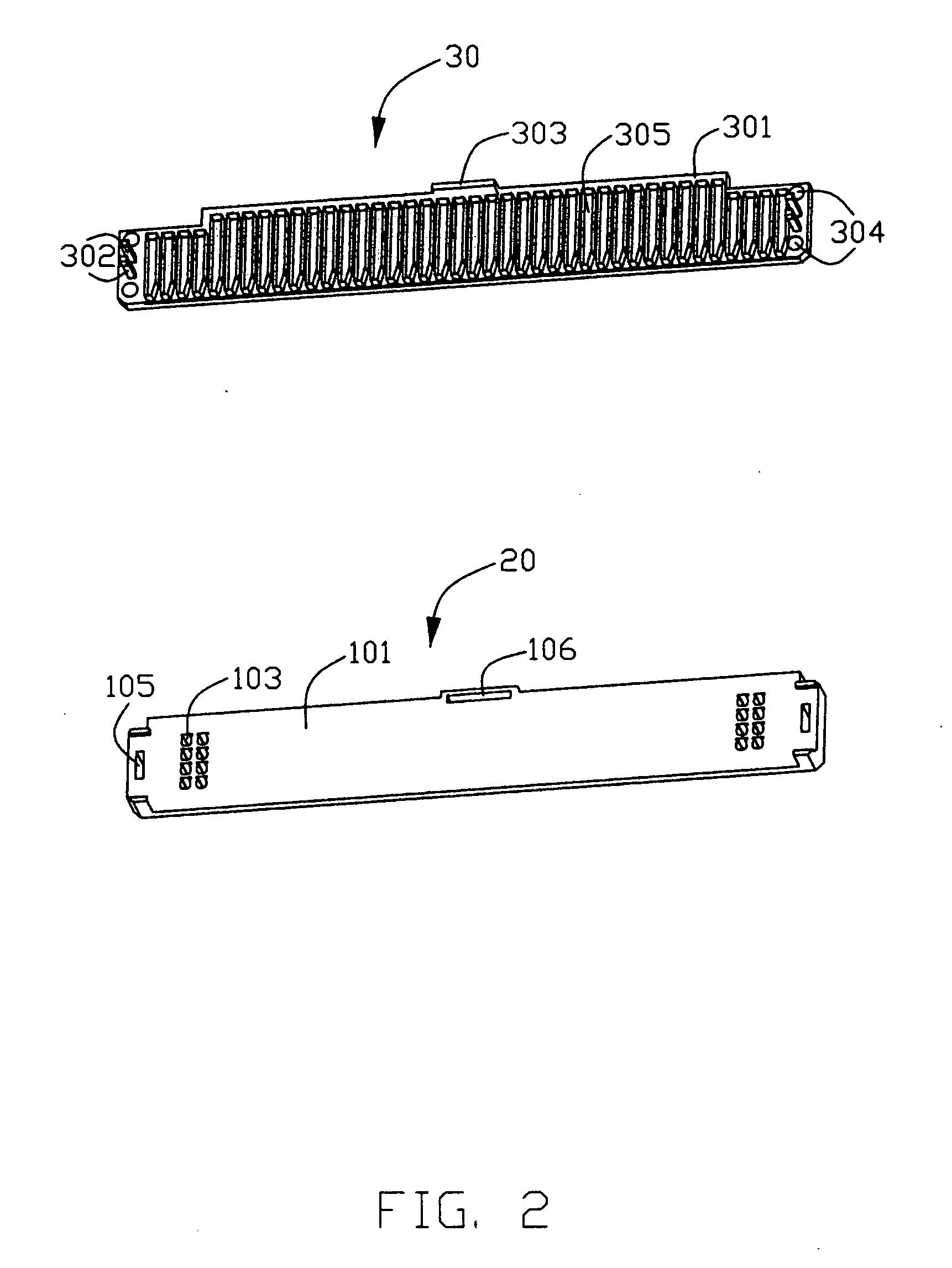
[0015] Referring to FIGS. 1 to 6, an LGA socket connector 1 according to the preferred embodiment includes an insulative housing 10 having a plurality of terminals 20 assembled therein, a floating cover member 30 movably mounted above the base 10, and a plurality of compressing springs 40 supported between the housing 10 and the floating cover member 30.

[0016] The insulative housing 10 is generally of a rectangular shape, and has a base defining a top mating interface 100 adapted to face the floating cover member 30, and a mounting interface 101, which is adapted to face a printed circuit board (not shown). A plurality of passageways 103 is arranged in columns and rows and extends through the housing base 10 from the mating interface 100 toward the mounting interface 101. Around the passageways 103, the base 10 is provided with two pairs of blind holes 104 respectively at opposite ends thereof. The blind hole 104 has a predetermined height thereof extending from the mating interfac...


PUM


Abstract

Disclosed is an electrical connector assembly including an insulative housing (10) with a plurality of passageways (103) therethrough from a top mating interface (100). A plurality of terminals (20) is inserted into the passageways with upper connecting portions (202) thereof have projections overlapped. A floating cover (30) is movably mounted above the base, and defines at least one slot (305) extending in a row direction along which, from a top view, the whole upper connecting portions direct to. The slot is configured to allow for upper mating sections (2021) of the whole row of terminals to be simultaneously extended therethrough when the floating cover is pressed downwardly to engage with the base. Thus, no damage will bring to the terminals that have overlapped configuration.

Description

BACKGROUND OF THE INVENTION [0001] 1. Field of the Invention [0002] The present invention relates to an electrical socket connector, and more particularly to an LGA socket with floating cover member for protecting terminals from being damaged during transporting process. [0003] 2. Background of the Invention [0004] The development of the connector industry toward the miniaturized, high-density and more reliable trends has required many connectors, especially LGA sockets, to be arranged in a high-density manner to keep up with the trends. The LGA socket is one of the most favorable and user-friendly products for electrical connection of a chip package and a printed circuit board. Effective electrical connection between the chip package and the printed circuit board is formed by continuous pressure against the package mounted on the LGA socket. [0005] The LGA socket generally includes a base defining a receiving space for receiving the chip package therein. A plurality of terminals is...

Claims


Application Information

Patent Timeline
IPC IPC(8): H01R12/00H01R12/14H05K7/10
CPCH01R12/57H01R13/24H01R13/4538H05K7/1069H01R12/716
Inventor LIAO, FANG-JWU
Owner HON HAI PRECISION IND CO LTD
Learn More