Automatically configured hydraulic support pillow

Inactive Publication Date: 2006-06-15
HEATH CLIFTON CURRY
View PDF10 Cites 22 Cited by
  • Summary
  • Abstract
  • Description
  • Claims
  • Application Information

AI Technical Summary

Benefits of technology

[0020] Based on the hydraulic effect of Pascal's Principle that an enclosed fluid under pressure exerts that pressure throughout its volume and against any surface in which it is contained, the device herein disclosed is a multi-chambered hydraulic pillow using differently shaped and sized, variably

Problems solved by technology

While the inflatable component allows control of the setting of the height of the neck and head support functions of the bolster component and is a key intent of the design, it creates a problem with utilization of the device other than as designed for top surface over bottom surface configuration.
The result is a device that cannot be used upside down and still provide the expected benefits.
In addition, there is no method for altering the firmness of the bolster component.
As can be imagined, both the fixed usage position attribute and the fixed firmness of the bolster can be a distraction at the least and an annoyance at best since one is restricted to such positions and resultant comfort levels as are allowed by the design.
U.S. Pat. No. 5,771,514 filed on Jun. 30, 1998, envisioned as an adjustable contour pillow addresses the second issue of the firmness of the head to pillow interface, but like all of the contour pillows identified it leaves the primary issue of asymmetrical or bottom over top use unresolved as it has a defined top surface and bottom surface.
Portability of this configuration of the device for

Method used


Image

  • Automatically configured hydraulic support pillow
  • Automatically configured hydraulic support pillow
  • Automatically configured hydraulic support pillow

Examples


Embodiment Construction

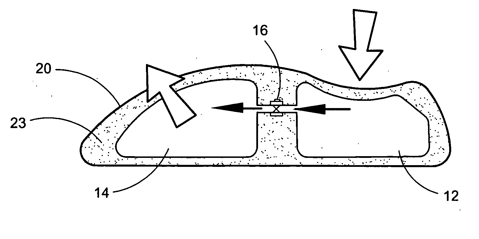
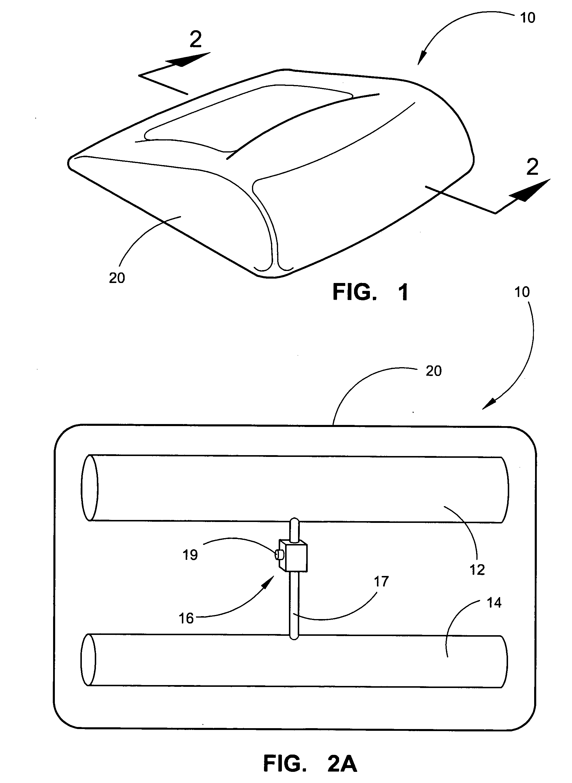
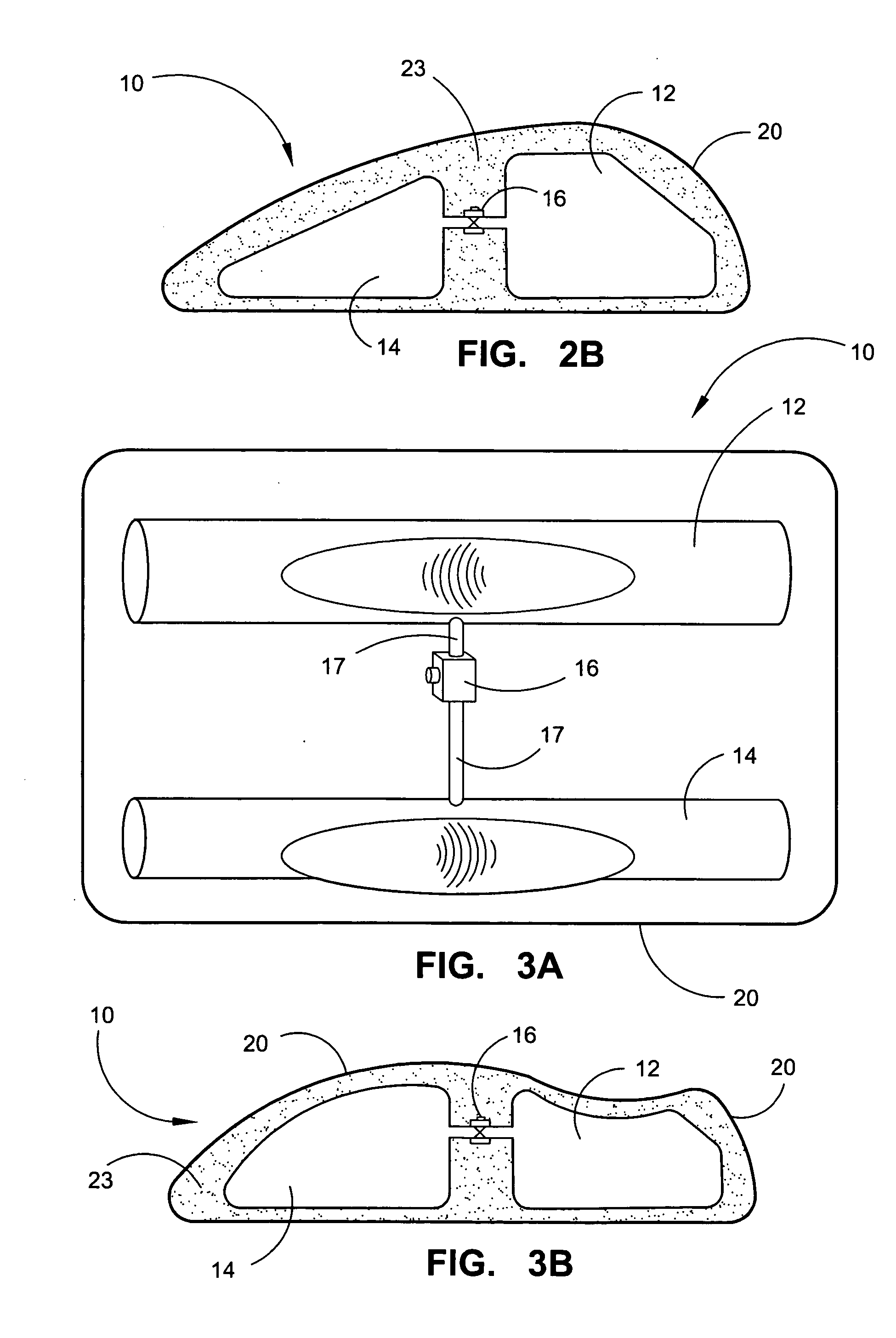
[0032] Referring now to the drawings, FIGS. 1-5 disclose the preferred embodiments of the herein disclosed pillow device 10. FIG. 1 depicts a preferred embodiment of the operating concept of the valved hydraulic support pillow device 10 of the invention which is described as composed of multiple self-contained fluid or gas filled elastic chambers, as shown in FIG. 2A, including first chamber 12 and a second chamber 14. The two chambers communicate with each other through a conduit 17 which also employs a means to control fluid flow direction from the second chamber 14 only toward the first chamber 12, which in this case is a valve 16 allowing fluid flow only in one direction toward first chamber 12 when in contact with a person's head 22 and internal pressures of the two chambers are not equalized. As shown in FIG. 1, there is an example, in this case asymmetrical, of a preferred embodiment of the device 10 as viewed from above and from the outside as it would appear once the user h...


PUM


Abstract

A pillow providing automatic adjustment of exterior dimensions to accommodate the shape and weight of the head of a user placed upon it. The pillow employs at least one reservoir chamber which provides liquid to at least one communicating receiving chamber through a conduit therebetween. Flow of the fluid is regulated to flow in one direction until the two chambers equalize and provide the desired head support dimensional characteristics to the user.

Description

BACKGROUND OF THE INVENTION [0001] 1. Field of the Invention [0002] The present invention relates to but is not limited to the field of pillows, cushions, mattresses and other reclinatory furniture devices of any type attached or otherwise utilizing a centrally placed, variably flexible, valved, single or multi-chambered, liquid-filled, hydraulically activated and valvically controlled method for support of the head or body. Devices such as those described herein are intended primarily for use during periods of travel, relaxation, reconstitution and rehabilitation and for potential orthopedic enhancements therein. [0003] 2. Prior Art [0004] There is a substantial amount of prior art relating to the field of ergonomic, orthopaedic and other types of cranial, cervical and general physical support devices for the human body. Generally speaking, the historical intent and direction of these efforts is to provide support for the head, neck and spine which simulates the optimal position at...

Claims


Application Information

Patent Timeline
IPC IPC(8): A47G9/00
CPCA47G9/10A47G2009/008A61F5/01A61G7/072
Inventor HEATH, CLIFTON CURRY
Owner HEATH CLIFTON CURRY
Why Eureka
Try Eureka