Cartridge for cleaning compressed air in compressed air supply systems of motor vehicles

a technology for cleaning compressed air and compressed air supply systems, which is applied in the direction of air treatment devices, colloidal chemistry, separation processes, etc., can solve the problems of affecting the reliability of the elements of the compressed air system located downstream, affecting the effect of affecting the reliability of the compressed air system, etc., to achieve the effect of improving the effect of coalescing filter, reducing the danger of clogging, and simplifying introduction and assembly

Active Publication Date: 2006-06-15
HALDEX BRAKE PROD AB
View PDF22 Cites 51 Cited by
  • Summary
  • Abstract
  • Description
  • Claims
  • Application Information

AI Technical Summary

Benefits of technology

[0015] However, with the novel method and the novel replaceable cartridge, it is possible to reduce continued transfer of especially fine mists through the compressed air supply system and towards the valves and other elements located therein during an increased usable lifetime of the cartridge.
[0016] According to the novel method, the compressed air to be cleaned is first guided through a pre-filter, then through a coalescence filter (also called coalescing filter herein) and afterwards through a deposit zone including a treating substance. The pre-filter serves to collect and deposit larger particles and cluster-like units, especially water drops, oil drops and coke particles. These particles to be removed are especially such ones which have a negative effect on the function of the coalescing filter and which may cause accelerated clogging of such a filter. In the novel cartridge, the pre-filter is located upstream of the coalescing filter to only introduce smaller particles (especially in the form of oil mist, water mist and the like) into the coalescing filter. The coalescing filter is capable of maintaining its functionality over a longer period of time with respect to such small particles such that the usable time period of the novel cartridge is increased. The function of the coalescing filter is also important for the deposit chamber being filled with a treating substance. In the deposit chamber, it is substantially humidity which is deposited. Due to the novel method, this third cleaning step also securely fulfills its full function.
[0019] The coalescing filter being arranged in the novel cartridge is no longer arranged at the entrance side as it is known in the prior art, but instead downstream of the pre-filter. The pre-filter is designed in a way that it is capable of collecting and depositing larger particles such that the coalescing filter being located downstream thereof is only subjected to smaller particles. In this way, it is possible to design the coalescing filter as desired for the respective load such that the danger of clogging effects is substantially reduced and the functionality is maintained during long periods of time. This is especially the case since the collected and agglomerated particles do not flow through the coalescing filter during regeneration.
[0020] To improve the effect of the coalescing filter, the coalescing filter may be substantially arranged at a vertical orientation in the housing. The coalescing filter at its exit side includes a collecting chamber for larger particles to be deposited. The collecting chamber is connected to the bypass conduit through which the regeneration air flows during regeneration, while there is no flow in the bypass conduit during the load phase.
[0021] The coalescing filter may be arranged in an insert. Such an arrangement simplifies introduction and assembly of the replaceable cartridge with its single components.
[0022] In addition to the first check valve, a second check valve may be arranged in the region of the coalescing filter and of the bypass conduit, respectively. The second check valve is arranged to open in the opposite direction, and it prevents a partial flow of air through the coalescing filter during regeneration.

Problems solved by technology

The impurities contained in the compressed air have a negative influence on the reliability of the elements of the compressed air system located downstream, especially valves.
Especially when tight flow cross-sections at the valves and at other elements of the compressed air system are used, these elements tend to clog.
Especially during wintertime, introduced humidity can condense and freeze which has a negative effect on the functionality of the elements located downstream.

Method used


Image

  • Cartridge for cleaning compressed air in compressed air supply systems of motor vehicles
  • Cartridge for cleaning compressed air in compressed air supply systems of motor vehicles
  • Cartridge for cleaning compressed air in compressed air supply systems of motor vehicles

Examples


Embodiment Construction

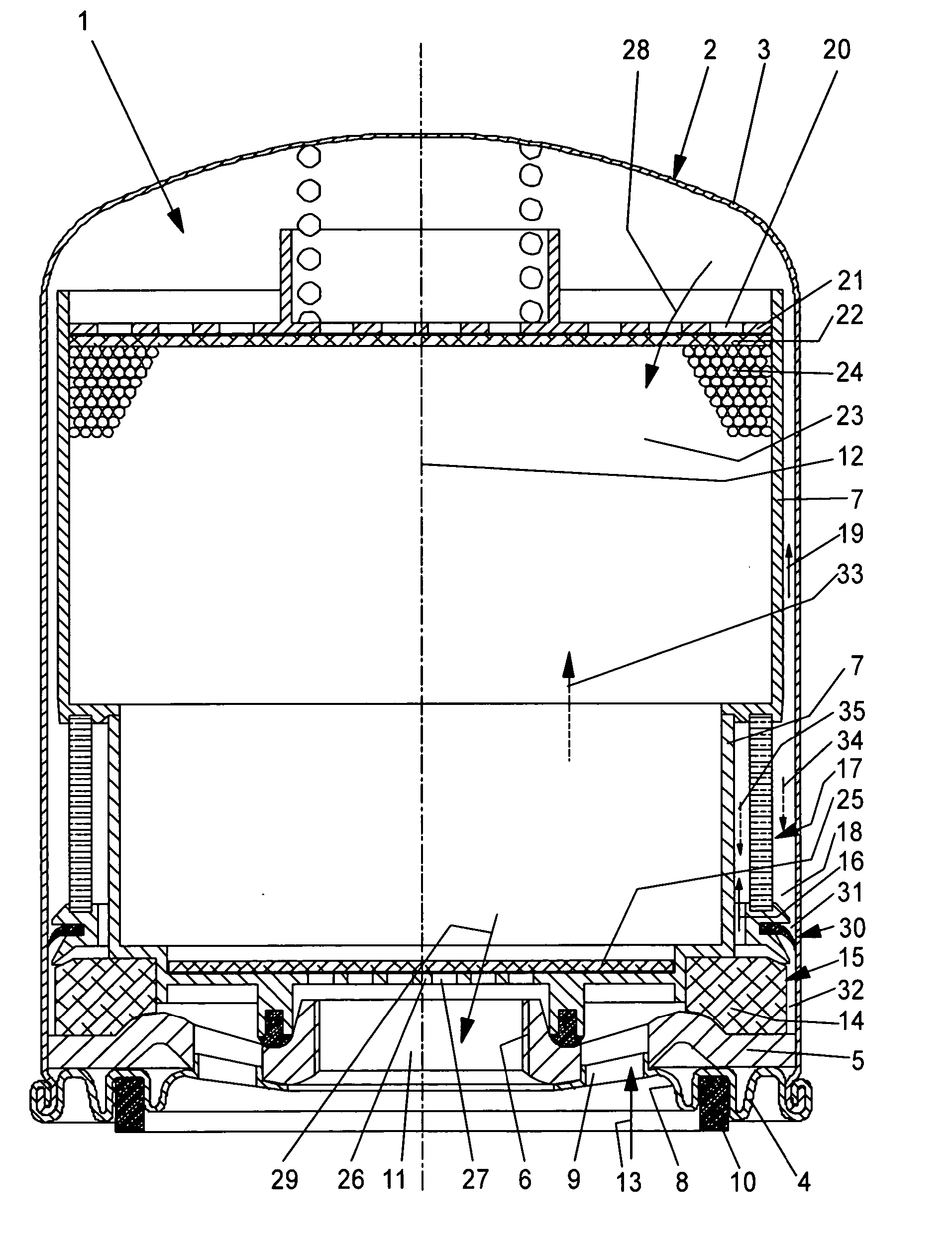
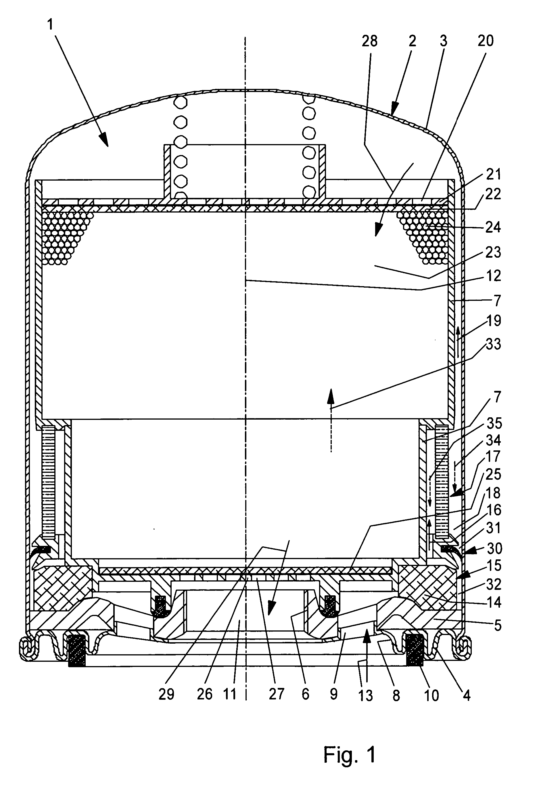
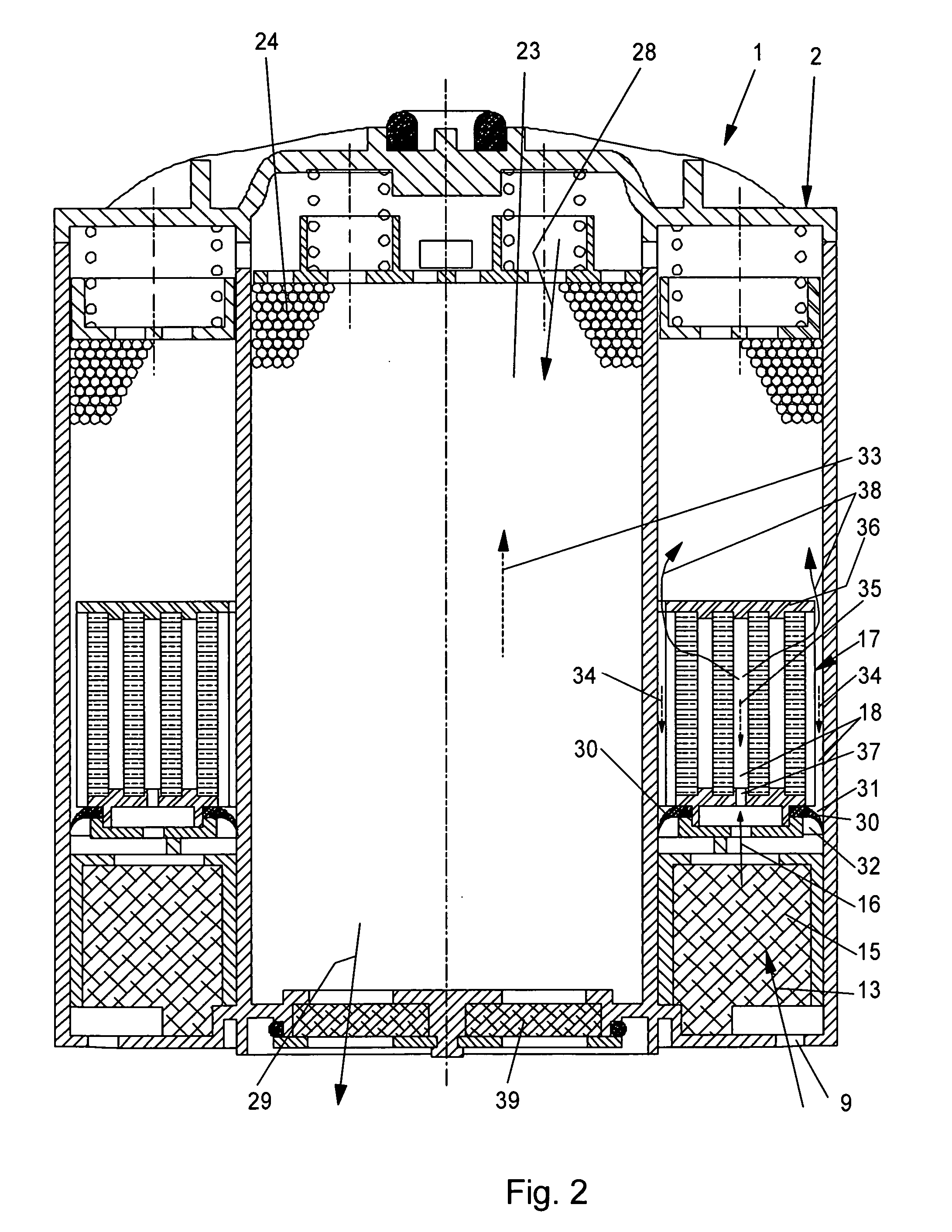
[0030] Referring now in greater detail to the drawings, FIG. 1 illustrates a novel cartridge 1. The cartridge 1 is designed as a replaceable unit to be assembled with a base unit to form an air dryer of a compressed air supply system of a motor vehicle (not illustrated). The cartridge 1 includes a housing 2 including a plurality of interconnected elements. The housing 2 includes an outer housing including a plurality of sheet elements 3, 4 which are interconnected by rolling. A cover 5 having a threaded connection 6 is located in the outer housing. An inner wall 7 having a stepped design is located in the housing 2. A face wall 8 including an opening 9 is located next to the cover 5 in a lower region. The face wall 8 includes a seal 10 which contacts the base element (not illustrated) when connecting the cartridge 1 to the base element by the threaded connection 6. The openings 9 located in the cover 5 are arranged to be distributed about the circumference. The threaded connection 6...


PUM

PropertyMeasurementUnit
sizeaaaaaaaaaa
velocityaaaaaaaaaa
poresaaaaaaaaaa

Abstract

A cartridge of an air dryer serves for cleaning compressed air to be used in compressed air supply systems of motor vehicles, especially trucks. The cartridge includes a housing, a pre-filter, a deposit chamber, a coalescing filter, a bypass conduit and a check valve. The deposit chamber is located downstream of the pre-filter. The deposit chamber is filled with a treating substance. The coalescing filter is arranged between the pre-filter and the deposit chamber. The bypass conduit is designed and arranged to bypass the coalescing filter and not to bypass the pre-filter. The check valve is arranged in the bypass conduit in a way that it opens during regeneration of the cartridge.

Description

CROSS-REFERENCE TO RELATED APPLICATIONS [0001] This application claims priority to co-pending German Patent Application No. DE 10 2004 059 508.9 entitled “Verfahren zum Reinigen von Druckluft an Druckluftbeschaffungsanlagen von Kraftfahrzeugen sowie Kartusche hierfür”, filed Dec. 10, 2004. FIELD OF THE INVENTION [0002] The present invention generally relates to a cartridge for cleaning compressed air in compressed air supply systems of motor vehicles. The present invention also relates to a method for cleaning compressed air being used in compressed air supply systems of motor vehicles. BACKGROUND OF THE INVENTION [0003] A method for cleaning compressed air in a compressed air supply system of a motor vehicle is known from the PCT Application published under WO 01 / 26783 A1 and corresponding to No. U.S. Pat. No. 6,723,154 B2. The compressed air coming from a compressor and especially including oil and water is cleaned by first passing it through a pre-filter, then through a layer of ...

Claims


Application Information

Patent Timeline
Patent Type & Authority Applications(United States)
IPC IPC(8): B01D46/00
CPCB01D53/0415B01D53/261B01D53/266B60T17/004Y10S55/17
Inventor HEER, SIEGFRIED
Owner HALDEX BRAKE PROD AB
Why Eureka
Try Eureka