
Inlet baffle arragement for gas/liquid separation; apparatus; and methods

a technology of gas/liquid separation and inlet baffle, which is applied in the direction of separation process, dispersed particle separation, chemistry apparatus and process, etc., can solve the problem that housings with tangential inlets are relatively expensive to manufactur

Inactive Publication Date: 2006-06-15
DONALDSON CO INC
View PDF29 Cites 28 Cited by
  • Summary
  • Abstract
  • Description
  • Claims
  • Application Information

AI Technical Summary

Benefits of technology

[0008] The preferred arrangement includes a radial vane positioned between the downcomer channel and the gas flow inlet at a position to cause gas flow to go through a radial arc or path of at least 70° typically at least 180°, before the gases can pass through the downcomer channel. For certain of particular embodiments depicted, preferably the path is defined to be at least 230°.
[0009] A variety of specific preferred configurations and features are described.
[0004] According to the present disclosure a gas / liquid separator assembly is provided. The assembly in general includes a vessel and a preseparation assembly. In use the assembly also includes at least one removable and replaceable; i.e., serviceable, separator element.
[0011] The disclosure also relates to methods of assembly and use. In particular a method of assembly would involve positioning a preseparation assembly or inlet baffle arrangement as defined above, inside of a vessel for gas / liquid separator assembly, to define a preferred inlet annulus and other features. A preferred method of use involves directing gas flow having liquid therein, through a preseparation assembly as defined, and then through a serviceable separator element. Such a method would typically include collecting at least a portion of separated liquid in a lower sump within the gas / liquid separator assembly. The method would preferably include directing the gas flow into the preseparation assembly as described.

Problems solved by technology

In general, housings having tangential inlets are relatively expensive to manufacture, by comparison to the second type of gas inlet discussed below.

Method used


Image

  • Inlet baffle arragement for gas/liquid separation; apparatus; and methods
  • Inlet baffle arragement for gas/liquid separation; apparatus; and methods
  • Inlet baffle arragement for gas/liquid separation; apparatus; and methods

Examples


Embodiment Construction

I. General Background

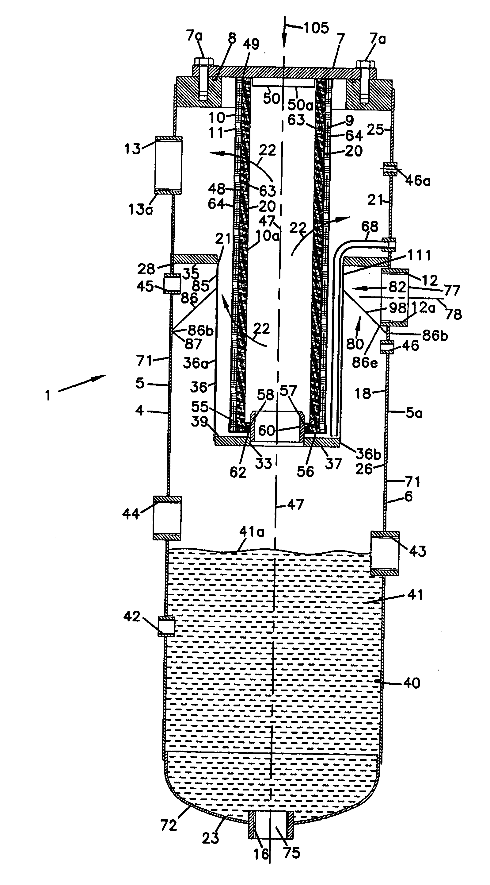
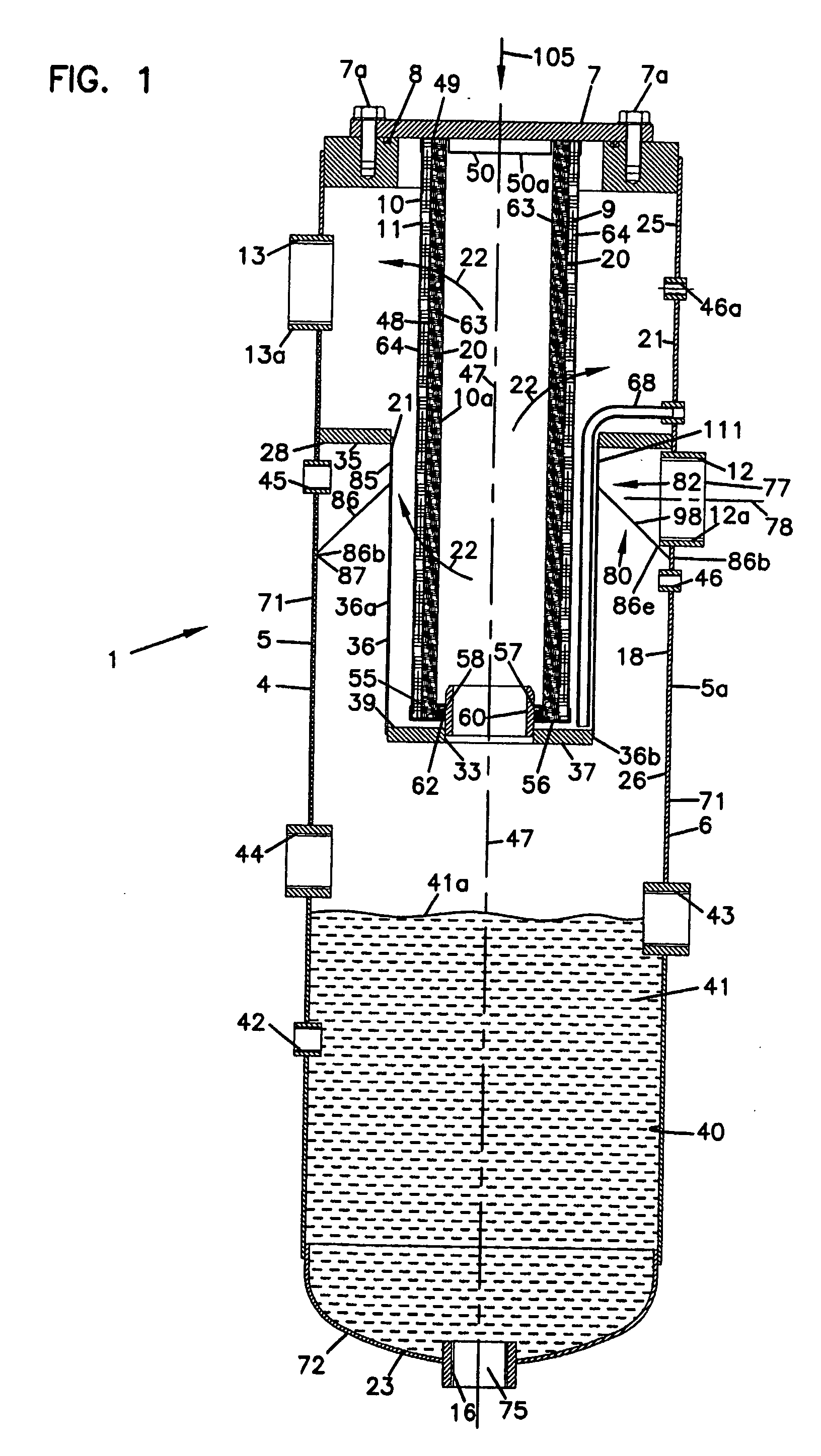
[0024] In general, gas / liquid separator assemblies of the type of concern herein, include three general components: a vessel arrangement; an inlet baffle arrangement; and, an internally received, removable and replaceable, (i.e., serviceable) separator arrangement. The internally received, removable and replaceable, (i.e., serviceable) separator arrangement generally comprises one or more separators (or separator elements) that, in time, are removed and replaced during servicing operations; hence the term “serviceable.” Each serviceable separator element includes a media pack, through which the gases are passed. Each media pack typically includes layers of media for coalescing and drain steps.

[0025] Herein, gas / liquid separator assemblies or separator-elements will be classified as either “in-to-out flow” or “out-to-in flow,” depending on whether, in use, during gas flow through the media pack of each separator element, gas flow is directed from an outside of t...


PUM

PropertyMeasurementUnit
Fractionaaaaaaaaaa
Fractionaaaaaaaaaa
Fractionaaaaaaaaaa

Abstract

A gas / liquid separator assembly (1) is provided, the assembly (1) generally comprises a vessel (4) with an internally received serviceable separator element (9) arrangement. A unique inlet baffle arrangement (80,82) is provided to facilitate preseparation of liquid from gases, as gases are passed through the assembly (1). The assembly (1) is particularly adapted for use in air / oil separation, for example for compressors. Methods of assembly and use are also described.

Description

[0001] This application is being filed as a PCT International Patent Application in the name of Donaldson Company, Inc., a US national corporation and resident, (Applicant for all countries except US) and Brian Read, a US resident and GB citizen (Applicant for US only), on 05 Dec. 2003, designating all countries and claiming priority to U.S. Ser. No. 60 / 431,432 filed on 06 Dec. 2002.FIELD OF THE INVENTION [0002] The present disclosure relates to gas / liquid separations. The disclosure particularly concerns an inlet baffle arrangement for use during a gas / liquid separation. It also concerns an apparatus for gas / liquid separation which utilizes a preferred inlet baffle, and methods of separation. A particular, useful, application is in an air / oil separator for air compressors. BACKGROUND [0003] Certain gas / liquid separation assemblies, for example as used with air compressors, include two general components: a vessel with a cover; and, a removable and replaceable (i.e., serviceable) se...

Claims


Application Information

Patent Timeline
IPC IPC(8): B01D50/00B01D45/06B01D45/08B01D46/24
CPCB01D45/06B01D45/08
Inventor READ, BRIAN
Owner DONALDSON CO INC
Features
  • Generate Ideas
  • Intellectual Property
  • Life Sciences
  • Materials
  • Tech Scout
  • Unparalleled Data Quality
  • Higher Quality Content
  • 60% Fewer Hallucinations
Learn More