
Steering device for pallet truck

Inactive Publication Date: 2006-06-15
GRAND STEER
View PDF20 Cites 14 Cited by
  • Summary
  • Abstract
  • Description
  • Claims
  • Application Information

AI Technical Summary

Benefits of technology

[0004] The present invention is a device attachable to a pallet jack for facilitating steering and positioning of the pallet jack. The device includes a housing structure having at least one roller partially disposed therein for contacting the ground. The housing structure attaches to an underside of a support member by way of a clamping mechanism. The clamping mechanism includes a spacer plate disposed between the housing structure and a locking plate. A threaded fastener connects and urges the locking plate and the housing structure together to clamp against a flange connected to the support member. The pallet jack is positionable between a raised position and a lowered position by means of a hydraulic mechanism. The hydraulic mechanism is connected to a main wheel and extensible rollers terminally positioned on the support member. While in the raised position, the extensible rollers and the main wheel contact the ground, defining a first turning radius of the pallet jack. Upon lowering the pallet jack, the rollers of the steering device engage the ground while the extensible rollers disengage the ground. Because the steering device is positioned between the main wheel and the terminally positioned extensible rollers, the resulting turning radius of the pallet jack is decreased thus allowing for better control and positioning of the pallet jack.

Problems solved by technology

However, by positioning the rollers at such a distance from the main wheel, the pallet jack is sometimes difficult to steer in tight or crowded work areas due to the fact that the turning radius of the pallet jack is defined by the distance between the main wheel and the rollers.
The turning radius of the pallet jack becomes especially problematic when the work area does not provide for adequate space, as is the case with crowded warehouses or storerooms.
Therefore, positioning the forked arms to engage the pallet is made difficult because very little lateral movement occurs at the terminal ends of the forked arms relative to lateral movement made at the opposing end having the main steering wheel.

Method used


Image

  • Steering device for pallet truck
  • Steering device for pallet truck
  • Steering device for pallet truck

Examples


Embodiment Construction

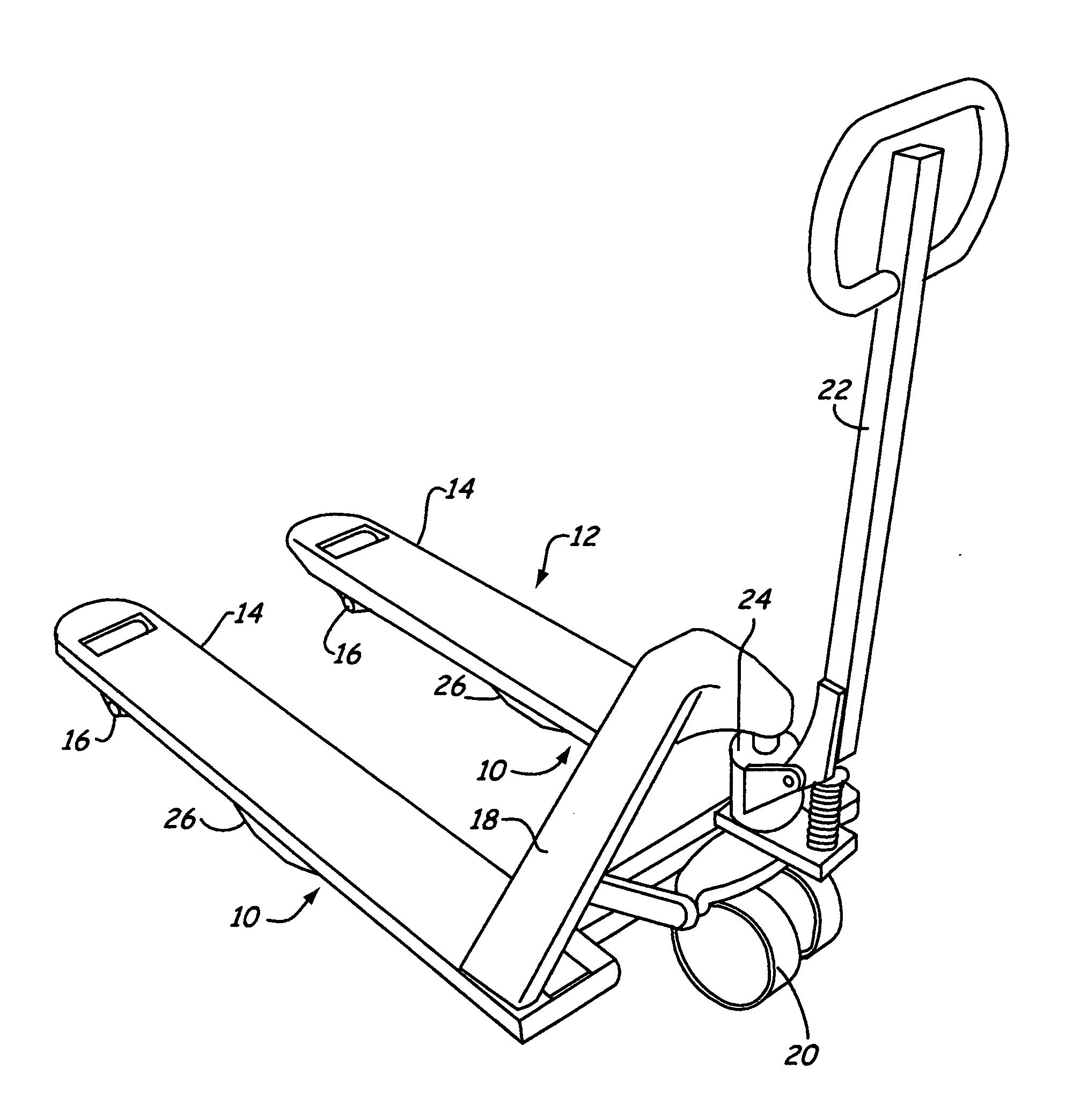
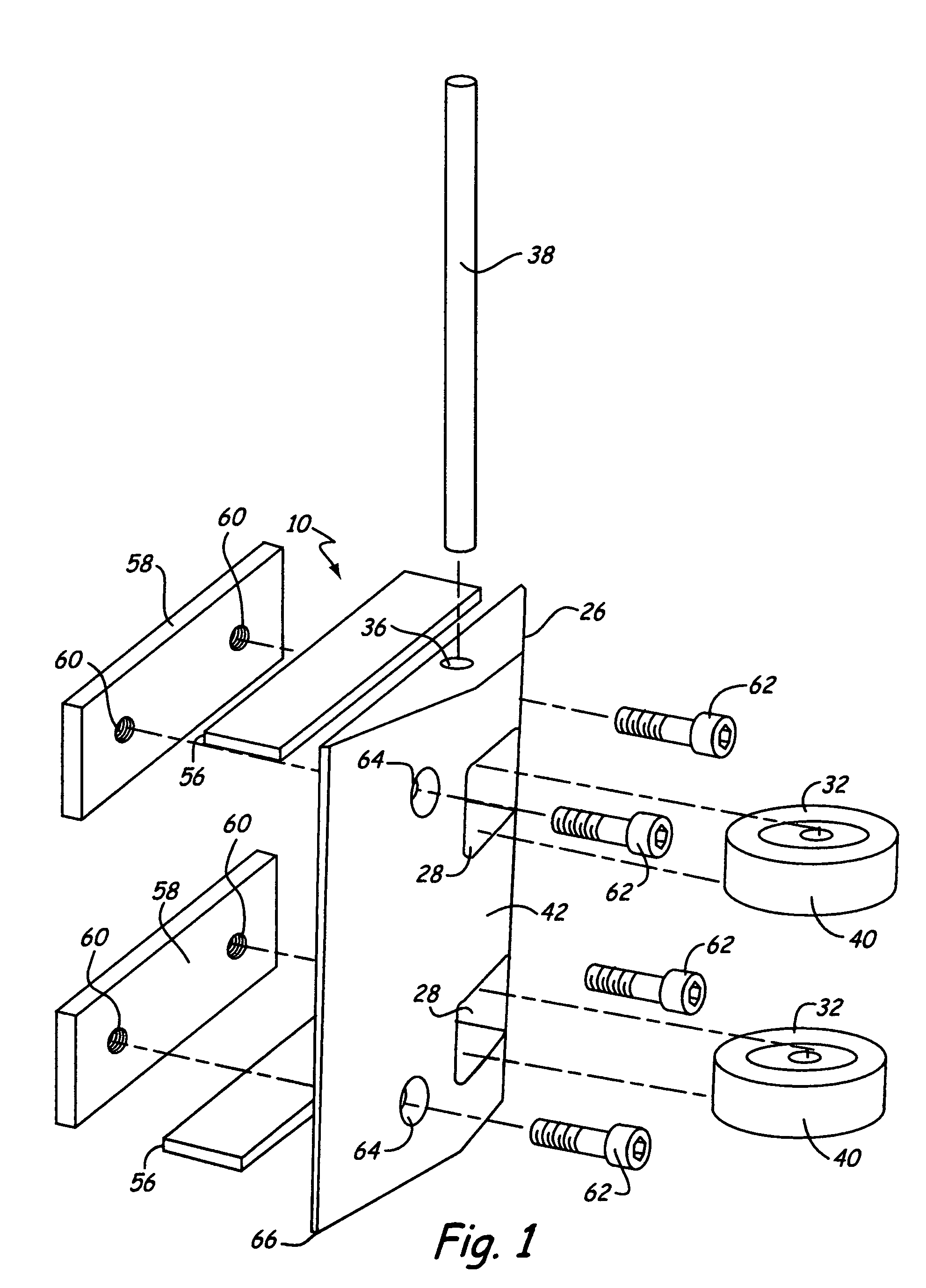
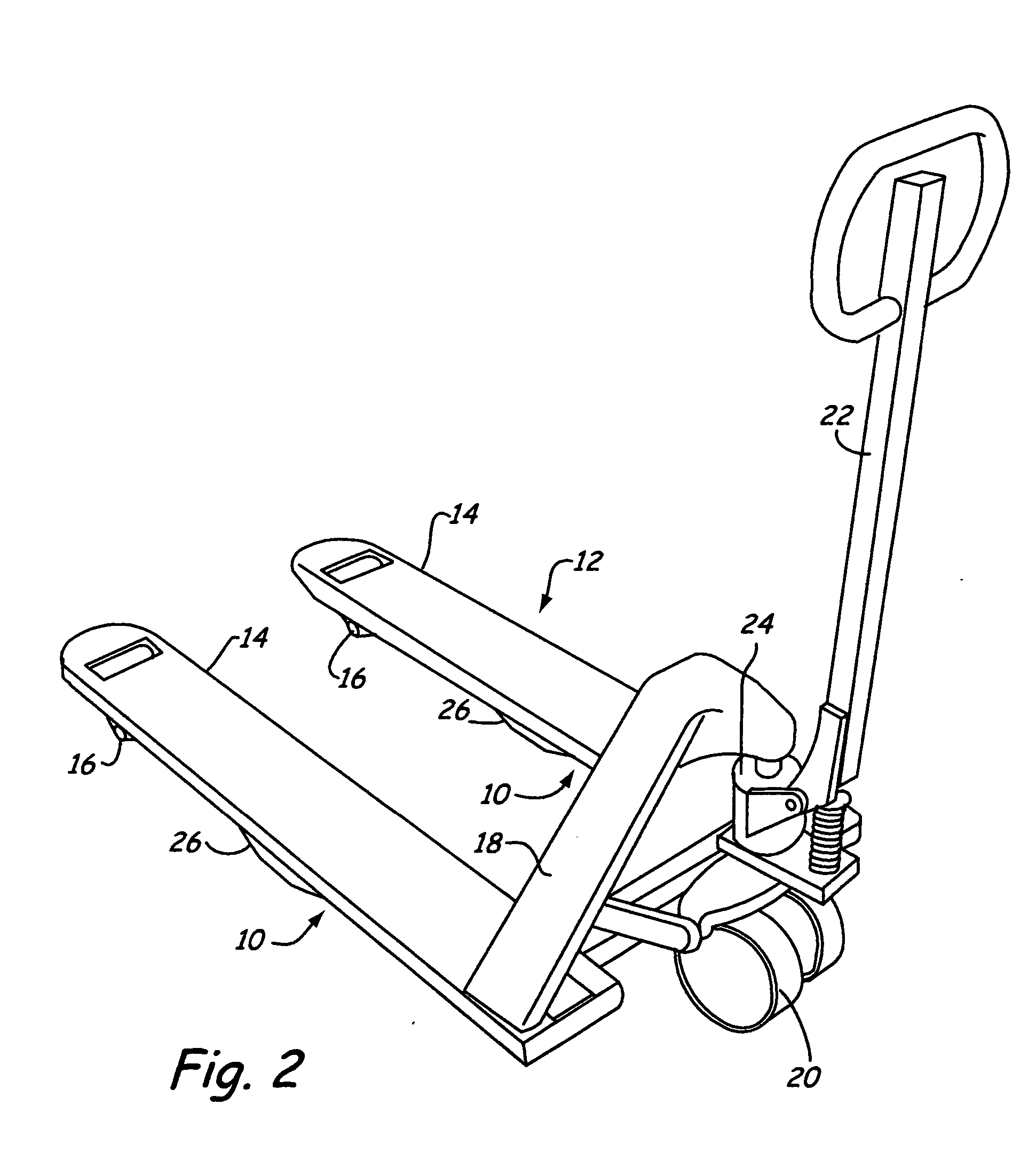
[0010] A steering device of the present invention is generally indicated at 10 in FIG. 1. The steering device 10 is preferably used in conjunction with material handling equipment, for example, a pallet jack 12 as illustrated in FIG. 2. The pallet jack 12, or hydraulic pallet truck, is a material handling device known to those skilled in the art of material handling for moving pallets (not shown) within a work area, such as a warehouse, storage room or within a manufacturing facility. For purposes of the present invention, an exemplary pallet jack 12 includes forked members 14 having extensible rollers 16 attached to an A-frame 18 having a positionable main wheel 20. The main wheel 20 connects to a steering rod 22 which also actuates a hydraulic lifting mechanism 24, operatively connected to the extensible rollers 16 and main wheel 20, for raising and lowering the pallet jack 12. In the lowered position, the pallet jack 12 can be positioned such that the forked members 14 are dispos...


PUM


Abstract

A steering device for decreasing a turning radius of a pallet jack includes a ground engaging member connected to a support member of the pallet jack between a main wheel and an extensible wheel. The load supporting member of the pallet jack is positionable between a raised position and a lowered position. A first turning radius of the pallet jack is defined by the distance between the main wheel and the extensible wheel. While the extensible wheel engages the ground when the support frame is positioned towards the raised position, positioning the support member towards the lowered position engages the ground engageable member with the ground causing the extensible wheel to disengage the ground. The main wheel and the ground engageable member then define a second turning radius which is less than the first turning radius.

Description

BACKGROUND OF INVENTION [0001] The present invention generally relates to pallet jacks. In particular, the present invention relates to a device for decreasing a turning radius of a pallet jack. [0002] In the art of material handling, pallets jacks typically include wheeled devices intended for the manual lifting of a pallet, with a load resting thereon, to transport the pallet and load from one work area to another. U.S. Pat. No. 4,589,669 discloses an exemplary pallet jack, or hydraulic pallet truck. Pallet jacks typically include forked support arms upon which extensible rollers are mounted at terminal ends. The opposing ends of the forked support arms are typically connected to one another and attached in some fashion to a pivotal wheel with a hydraulic lift. The pivotal wheel allows the user to steer the pallet jack when either pushing or pulling the palletjack. The hydraulic lift is operatively connected the wheel and the extensible rollers to raise and lower the support arms ...

Claims


Application Information

Patent Timeline
IPC IPC(8): B62D21/14
CPCB62B3/001B62B3/008B62B3/0606B62B2205/14B62B2301/00B62B2301/08
Inventor HARTMANN, FRED O.AASEBY, ALLEN C.
Owner GRAND STEER
Learn More