Vehicle accelerator and brake indicators

a technology of brake indicators and accelerators, which is applied in the direction of vehicle components, signalling/lighting devices, optical signalling, etc., can solve the problems of difficulty in judging whether the driver of an approaching vehicle intends to continue, the accelerator and brake lights in prior art systems are not provided adequately, and the front lights of vehicles are generally limited

Inactive Publication Date: 2006-06-15
SONG WON MOO
View PDF53 Cites 32 Cited by
  • Summary
  • Abstract
  • Description
  • Claims
  • Application Information

AI Technical Summary

Benefits of technology

[0034] Improved indicators for the use of brakes and accelerator for vehicles are disclosed. Visual indicators of braking, coasting and acceleration are visible from the front, sides and rear of a vehicle. An accelerator indicator for a vehicle is externally visible, but is not visible to an operator, and does not interfere with vehicle operation at night or under low visibility conditions. One or more indicator colors are chosen so as to be aesthetically pleasing. Indicator design and placement are also chosen so as to be aesthetically pleasing. Improved indicators are suitable for installation into any type or style of vehicle. Such improved indicators may be installed at manufacture time. Indicators may be positioned upon a vehicle in conventional locations. Improved indicators may be retrofitted into an existing light system of an existing vehicle. In one embodiment, improved accelerator and brake indicators comprise a housing including a reflective shell and one or more transparent or translucent lenses forming a sealed enclosure, a socket, at least one light producing element, a means to electrically connect a socket to the vehicle's electrical system, a means to electrically connect a socket to a logic device and sensor which are attached to the vehicle's accelerator system, and a means to electrically connect a socket to a logic device and sensor which are attached to the vehicle's brake system. The sockets and reflective shell are disposed in the housing. The sockets each have at least one light producing element or light bulb inserted therein. The means to electrically connect a socket to the electrical system allows a brake light to illuminate when the vehicle brakes are applied. The means to electrically connect a socket to the accelerator system of the vehicle allows an accelerator light to be illuminated when the accelerator is used.

Problems solved by technology

Lights on the front of a vehicle are generally limited to headlights, marker or running lights, and turn signal lights.
One problem exists when a following vehicle operator does not know whether the preceding operators of vehicles are using the vehicle's accelerator, or are coasting wherein the operator is using neither the accelerator nor brake.
Another problem exists wherein observers and operators of other vehicles who are positioned in front of a vehicle do not know whether the operator of the vehicle has engaged its brake system.
Sometimes it is difficult to judge whether the driver of an approaching vehicle intends to continue through a yellow semaphore light.
Prior art systems fail to adequately provide such accelerator and brake lights.
However, such a brake light does not communicate the state of the acceleration pedal of a vehicle.
Placement of an indicator solely in the front windshield of a vehicle would not be effective when a moving vehicle is observed from the side.
However, there is no disclosure of connecting these green lights to the accelerator of the vehicle.
Although the lights are mounted on the front of a vehicle, the lights are located at the bottom of the front bumper rather than being “high mounted” and do not communicate the state of the accelerator pedal.
However, there is no teaching of a forwardly visible indicator.
There is no teaching to mount such a device in a forward facing position.

Method used


Image

  • Vehicle accelerator and brake indicators
  • Vehicle accelerator and brake indicators
  • Vehicle accelerator and brake indicators

Examples


Embodiment Construction

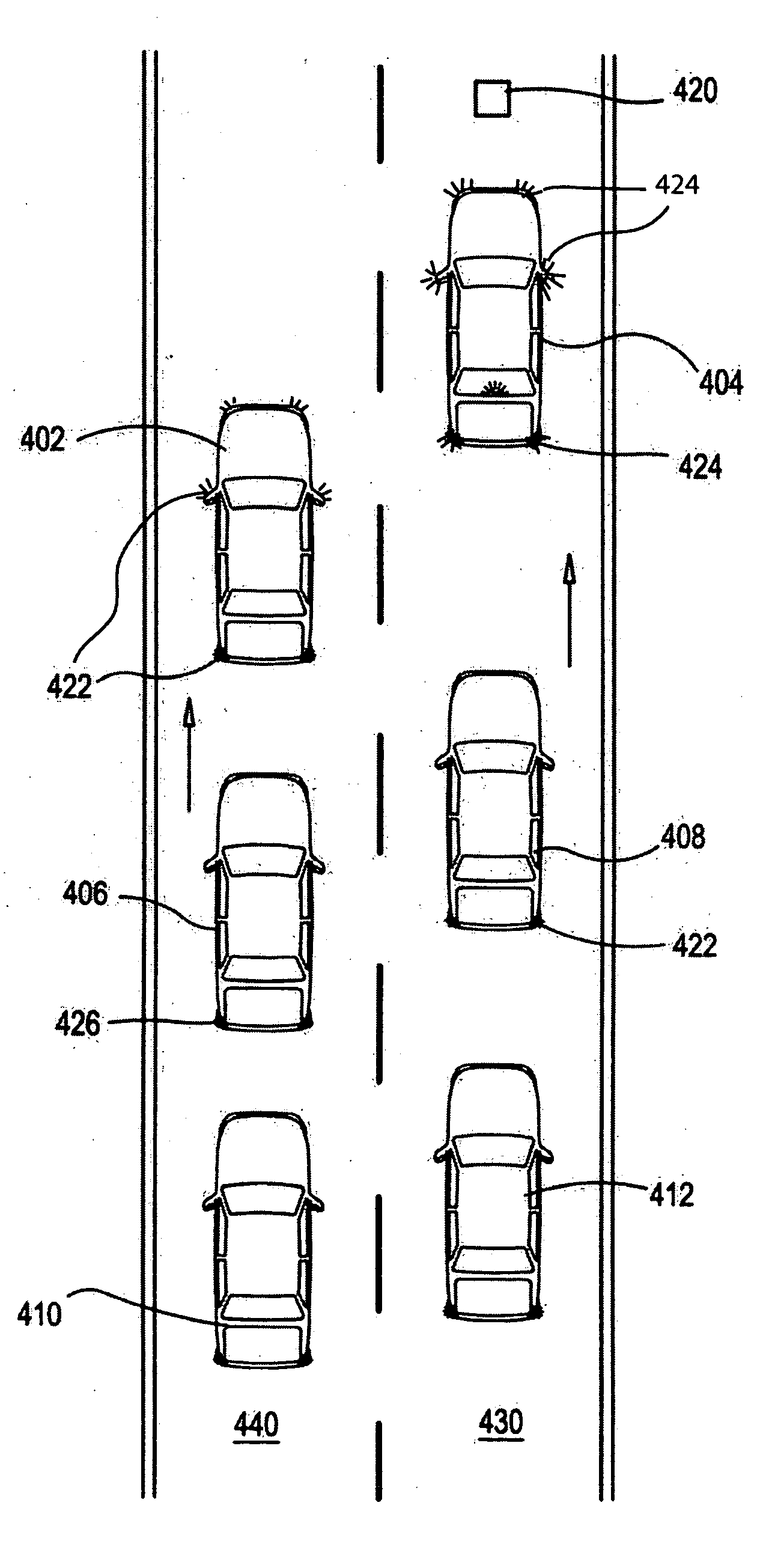
[0091] While the invention is described below with respect to one or more preferred embodiments, other embodiments are possible. The concepts disclosed herein apply equally to other systems for externally indicating acceleration, deceleration and braking of an automobile or other vehicle through detecting the use of a vehicle's brakes and accelerator. A vehicle may include any motor vehicle, automobile, mass transportation vehicle, truck, tractor trailer, bus, school bus, commercial vehicle, commercial equipment, industrial equipment, military vehicle, snowmobile, jetski, scooter, motorcycle, minibike, bicycle, go-cart, moped, unmanned vehicle, toy car, toy ship, or toy aircraft. It will be readily apparent to those skilled in the art that various modifications, rearrangements, and substitutions can be made without departing from the spirit of the invention. The scope of the invention is defined by the claims appended hereto.

[0092] An externally visible accelerator indicator instal...


PUM


Abstract

An improved accelerator and brake indicators for vehicles. Visual indicators of braking, coasting and acceleration are visible from the front, sides and rear of a vehicle. Such indicators may be used on any type of vehicle including cars, trucks, trailers, airplanes, motorcycles, bicycles, toy vehicles, etc. An accelerator indicator may be blue, green or any other color. An external accelerator indicator is not visible to an operator, and does not interfere with nighttime operation of vehicles. One or more indicator hues are chosen so as to be esthetically pleasing. Indicator design and placement are also chosen so as to be esthetically pleasing. Indicators are suitable for installation into any existing or future style of motor vehicle. Indicators may be positioned upon a motor vehicle in conventional and non-conventional locations. Preferentially, accelerator, brake, and running indicators comprise a housing including a reflective shell and one or more translucent lenses forming a sealed enclosure, a connector or socket, a removable light bulb or light emitting element, a means to electrically connect a socket to the brake light electrical system, and a means to electrically connect a socket to a sensor attached to the accelerator system of a motor vehicle.

Description

BACKGROUND [0001] 1. Technical Field [0002] This invention relates generally to the field of safety signal light systems installed on a vehicle, and more particularly to a set of colored lights indicating the use of brakes and accelerator or the lack of use thereof. [0003] 2. Background of the Invention [0004] Operating lights are used on all types of vehicles including, but not limited to, aircraft, cars, motorcycles, trucks, trains, bicycles, and toy vehicles. Brake lights of currently produced vehicles are typically red and are usually found only on the rear of a vehicle. Many vehicles also have red, yellow, orange or amber running lights. Such running lights are also on the front corners or sides of a vehicle. The intent of such lights is to provide higher visibility for vehicles. [0005]FIG. 1 illustrates the placement of rear facing lights on a typical motor vehicle according to the prior art. The description of the present invention refers to an automobile, but those having or...

Claims


Application Information

Patent Timeline
Patent Type & Authority Applications(United States)
IPC IPC(8): B60Q1/22B60Q1/44B60Q1/50B60Q1/26
CPCB60Q1/44B60Q1/442
Inventor SONG, WON MOO
Owner SONG WON MOO
Why Eureka
Try Eureka