

Image Display Apparatus
a technology of image display and display device, applied in the direction of instruments, static indicating devices, etc., can solve the problem of not correcting the data of the second region not in the vicinity, and achieve the effect of reducing costs and alleviating harmful effects
- Summary
- Abstract
- Description
- Claims
- Application Information
AI Technical Summary
Benefits of technology
Problems solved by technology
Method used
Image

Examples
first embodiment
[0059] The following will describe in detail the first embodiment of the present invention.
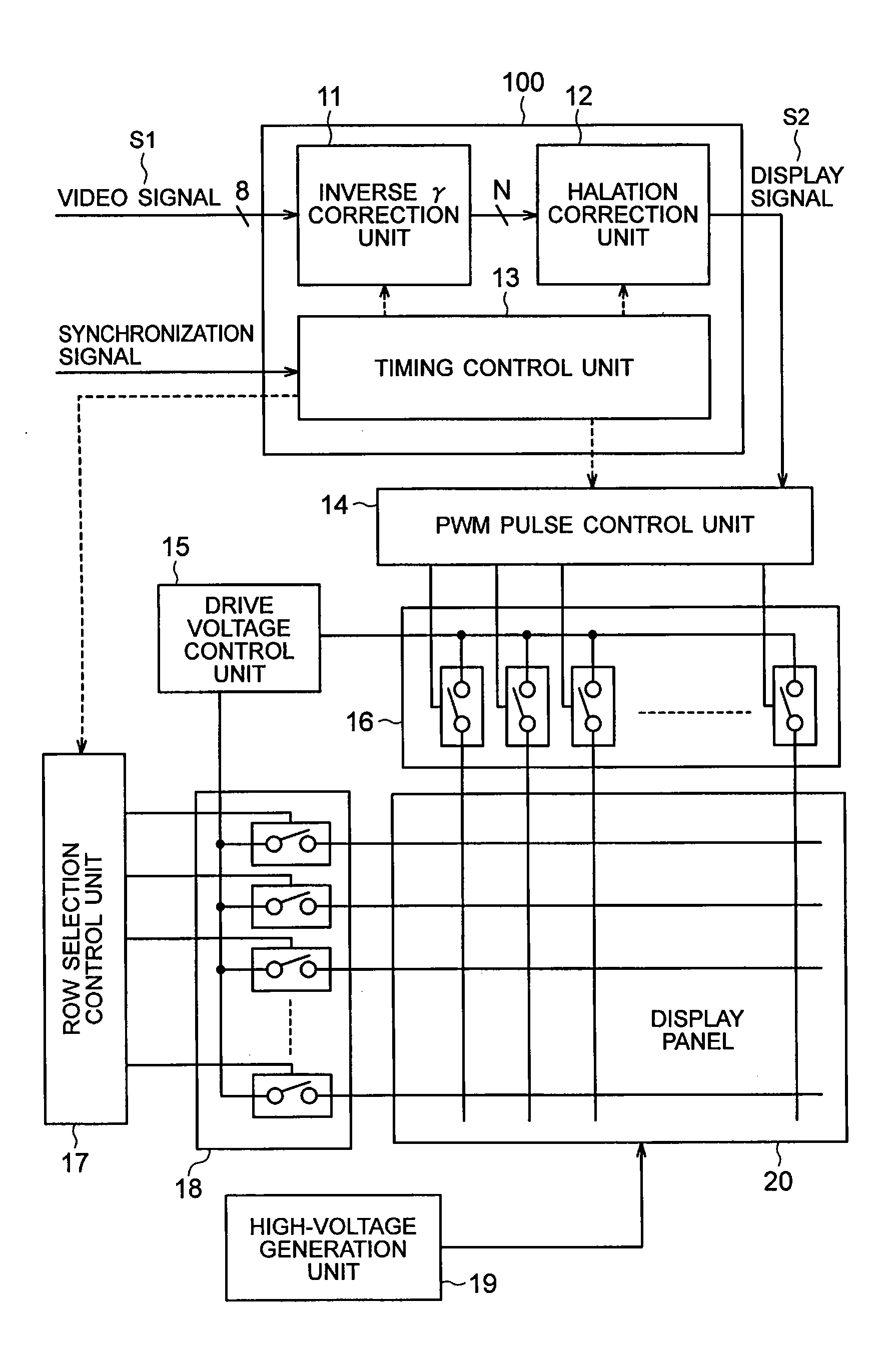
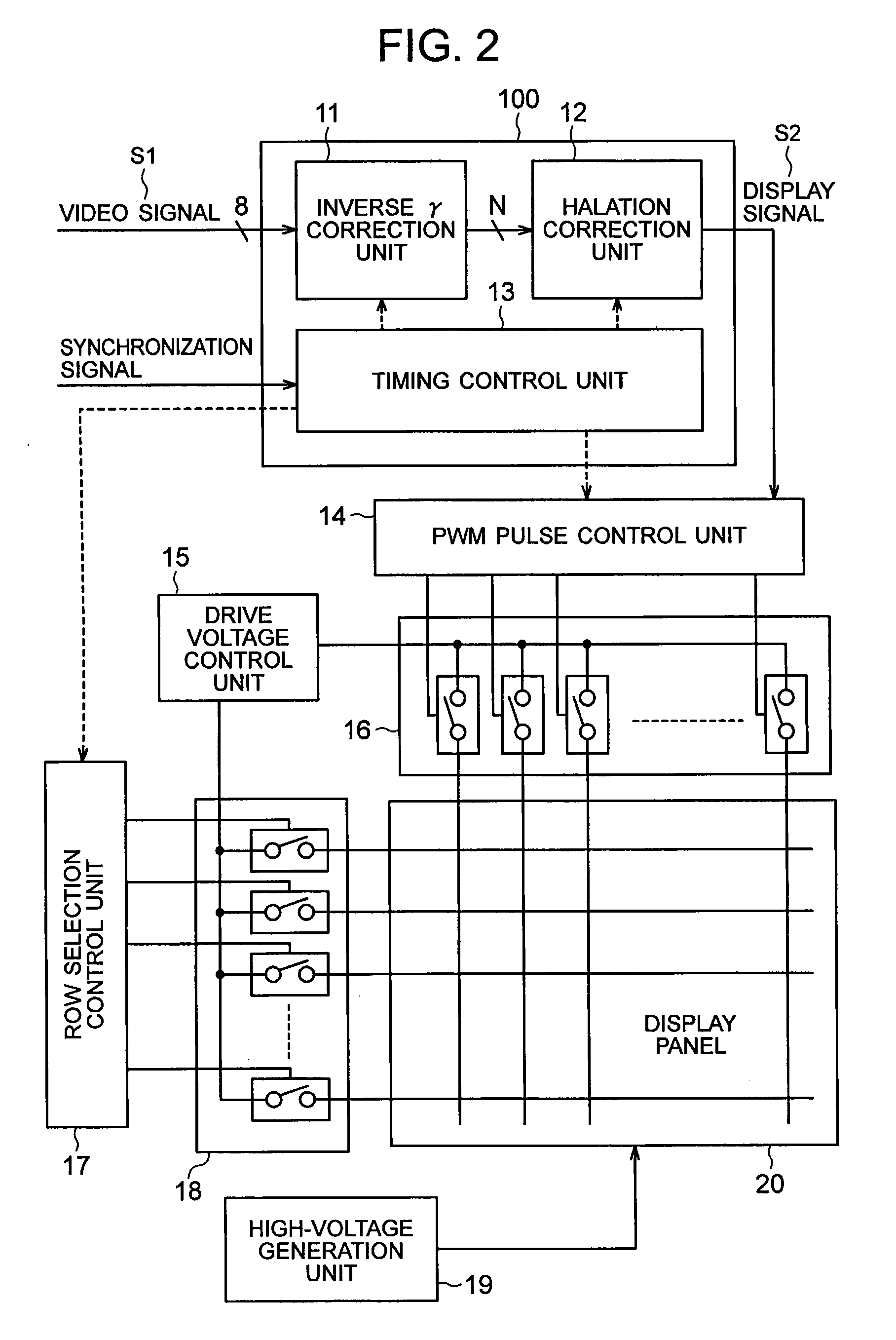
[0060] The present invention can be applied to a display apparatus using a surface conduction electron-emitting device, a field emission display apparatus (FED), a plasma display apparatus (PDP), an organic EL display apparatus, etc. In an electron beam display apparatus such as an FED or a display apparatus that uses a surface conduction electron-emitting device, there is a possibility that halation may be caused on a peripheral pixel by brightness of a luminescent spot that has self-emitted. Therefore the electron beam display apparatus is a preferable embodiment which the present invention may be applied to. The plasma display apparatus is another preferable embodiment to which the present invention may be applied, because there is a possibility of halation (cross-talk) occurring onto a peripheral pixel similarly if there is no barrier rib (which corresponds to “member”) between discharge ...
second embodiment
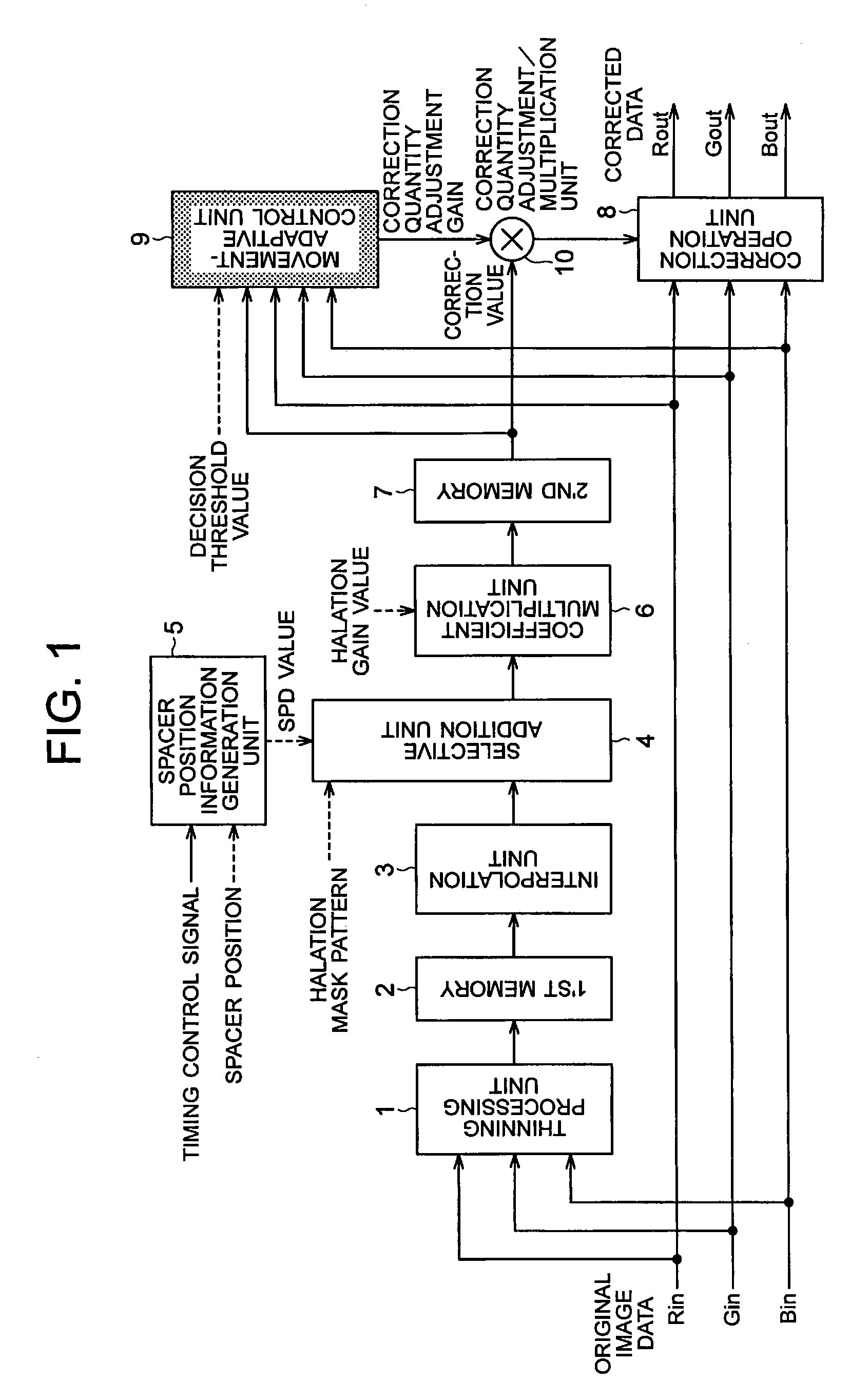
[0097] The first embodiment has been described about method for adjusting a correction value on original image data based on correction value and original image data with reference to a movement-adaptive halation correction. In the present embodiment, similar movement-adaptive halation correction is performed by using a plurality of correction values calculated in different frames respectively. A correction value adjustment method of the present embodiment is described with reference to FIG. 10. FIG. 10 is different from FIG. 1 in that a movement-adaptive control unit 9 references only an n'th frame correction value and an (n−1) 'th frame correction value but not original image data. And a delay unit 11 is added in FIG. 10. The present embodiment employs the same halation correction method as that of the first embodiment.
[0098] In FIG. 10, original image data is input in synchronization with an input vertical synchronization signal at a timing of T1 as shown in a timing chart of FI...
third embodiment
[0107] In the above embodiments, such a configuration has been described as to calculate a correction value that corresponds to a portion that does not have effect due to blockade by a spacer, of an increment in brightness that would have been given by a pixel positioned in the vicinity of a correction-subject pixel to brightness of the correction-subject pixel. The correction value obtained by this calculation is calculated with respect to correction-subject data in such a manner as to increase a magnitude of the correction-subject data.
[0108] The present embodiment, on the other hand, employs a configuration to calculate a correction value corresponding to an increment in brightness which a pixel positioned in the vicinity of a correction-subject pixel gives to brightness of the correction-subject pixel. In this case, brightness of a correction-subject pixel is corrected, using an obtained correction value, so that it decreases by as much as a quantity of an increment in brightne...
PUM
 Abstract
Description
Claims
Application Information